We have a confession to make: we love centrifuges. We’ve used all shapes and sizes, for spinning bags of whole blood into separate components to extracting DNA, and everything in between. Unfortunately, these lab staples are too expensive for many DIY-biologists unless they buy them used or build them themselves. [Pieter van Boheemen] was inspired by other DIY centrifuges and decided to make his own, which he named the RWXBioFuge.
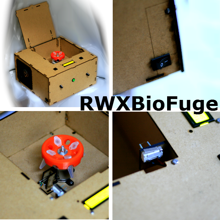
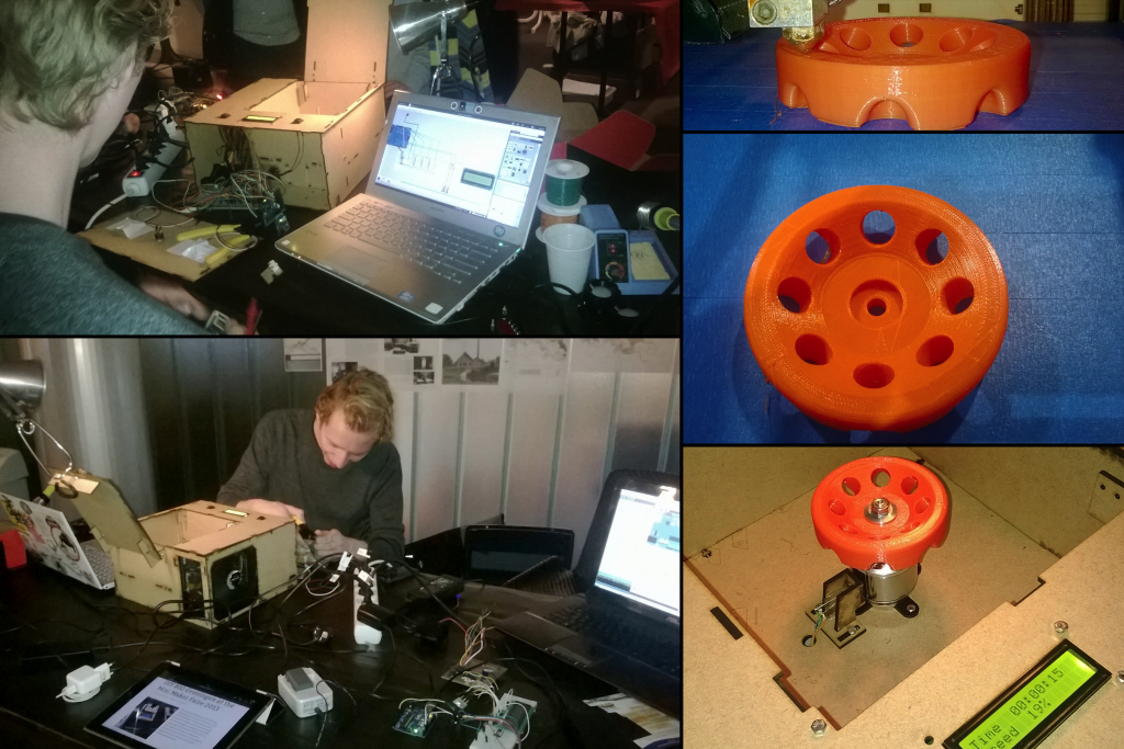
[Pieter] designed the RWXBioFuge using Sketchup, OpenSCAD, and InkScape. It features a Thermaltake SMART M850W ATX power supply, an R/C helicopter Electronic Speed Controller (ESC), and brushless outrunner motor. For user output it utilizes a 16×2 LCD character display with an I2C interface.The frame is laser-cut from 3mm MDF while the 3D-printed PLA rotor was designed with OpenSCAD.
An Arduino handles the processing side of things. [Pieter] used an Arduino Ethernet – allowing a web interface to control the centrifuge’s settings and operation from a distance. We can see this being useful in testing out the centrifuge for any rotor/motor balance issues, especially since [Pieter] states that it can be configured to run >10,000 rpm. We wouldn’t want to be in the room if pieces start flying off any centrifuge at that speed! However, we feel that when everything’s said and done, you should have a centrifuge you can trust by your side when you’re at your lab bench.
While there are similarities to the Openfuge, the larger RWXBioFuge has rotor capacities of eight to twenty 1.5-2.0ml microcentrifuge tubes. Due to the power supply, it is not portable and a bit more expensive, but not incredibly so. There are some small touches about this centrifuge that we really like. The open lid detector is always a welcome safety feature. The “Short” button is very handy for quick 5-10 second spins.
A current version of the RWXBioFuge is being used at the Waag Society’s Open Wetlab. [Pieter’s] planned upgrades for the next version include a magnetic lid lock, different rotor sizes, an accelerometer to detect an improperly balanced rotor, and optimizing the power supply, ESC, and motor setup. You can never have enough centrifuges in a lab, and we are looking forward to seeing this project’s progress!
Check out a few more pictures of the RWXBioFuge after the break.


Nice project. The rotor chamber being made of porous material seems less than ideal. Cut it out of acrylic or something else that wouldn’t mind being covered in ethanol and you’ve got yourself a nice benchtop centrifuge.
Yeah, a non-porous rotor chamber would be best.
I would suggest aluminum. Same thickness. It’s dimensionally more stable and can be finishes in a variety of ways. Plus it would contain things much better if things went awry.
Whoops. Can be finished.
How dangerous and fun! 10000 RPM isn’t too high for a centrifuge, but I wouldn’t run it without a better lid, heh. I suspect you to have to make sure your printer is pretty exact when making that centrifuge, gotta be careful.
These diy centrifuges are really an amazing step towards a better future, the more available simple tools are the more that can be done with them, an example of this can actually be seen in china, the government opened up rather good hackerspaces, and guess what? China’s economy is thriving, people are developing new technologies. Weather or not that is caused by the government hackerspaces is up for debate, but it’s still very cool. Education can only do so much if people don’t have the tools available to apply their knowledge.
*Whether* not weather.
Also, be very very careful with rotational energy like that…just sayin’. Here’s an example that is orders of magnitude larger, but note the damage to the room and structures.
http://www.chem.purdue.edu/chemsafety/newsandstories/centrifugedamages.htm
Great link. [Pieter] was conscientious enough to upload safety documents to his Github for the RWXBiofuge. I do hope that anyone who does build their own centrifuge tests it out on lower speeds before cranking the rpm’s up.
I have nothing against people building their own centrifuges (or any other piece of potentially dangerous kit), but they should always be aware of the risk involved. your link is the perfect demonstration that.
To extract one bit of information from that link for everybody to see: When a university ultracentrifuge failed, the resulting shock wave BLEW OUT THE WINDOWS OF THE ROOM IT WAS IN.
There’s a lot of energy in spinning metal. Be aware and keep yourself safe. Yes, I know this build doesn’t have a metal rotor, but eventually that’s where you have to go if you want a high quality centrifuge.
I think this particular centrifuge design is probably very unlikely to cause serious harm were it to fail. I do not think it can achieve the same G forces that an ultracentrifuge would get up to, because the lower diameter rotor, small sample volume, and relatively small motor sizes are all simply not large enough to cause grave harm.
Like I said – I know this doesn’t have a metal rotor. But making it known that centrifuges have spectacular failure modes is good.
Just to second what everyone’s saying about safety stuff. Normally I’m as sceptical of the elves ‘n safety as the rest of us but centrifuges are an exception. The rotor material is probably not a good idea because of the possibility of delamination between the printed layers. At the very least, I’d find a short section of steel pipe to place around the rotor to catch anything in case it does go south (or north, or east, or west).
Yes, the energy in a small thing like this is minimal, but I bet it could still give a decent fright if it burst! A 3mm MDF enclosure isn’t going to help much.
Centrifuge failures are rather spectacular. Some bigger centrifuges I’ve seen at university are remotely operated so nobody is near them when running. Pretty good idea, when they can walk through walls when the rotor bursts…..
They certainly wouldn’t help the aesthetics(or portability) any; but the humble sandbag has a pretty good track record for stopping projectiles on the cheap and low-tech.
Anyone have a ballpark estimate of whether modestly bulking up the enclosure (thicker material, use of steel pipe section, switch to alumiuminum or polycarbonate, etc.) would achieve adequate containment without excessive increase in cost or weight, or would it be better to just treat the interior enclosure as sacrificial/there for ease of cleanup and build a little bunker for it to inhabit?
Thanks for all the safety recommendations! I assume that anyone that’s capable of replicating the machine is also competent enough to work with it safely. The ethernet interface is supposed to used when testing the device, so you don’t need to set next to it while debugging.
The 3mm MDF could be replaced by any other material that you may prefer.
When the rotor comes fresh out of the printer, you can indeed hear the loose filaments on the side spinning of during the first run. So be careful with that.
Someone recommended me to link the lid switch directly to the power supply. So you can only operate the machine when the lid is closed. That might not be such a bad idea too.
Please send me a comment on Github when you decide to build your own!