For reasons we both agree with and can’t comprehend, most ‘prosumer’ SLR cameras don’t have mechanical shutter releases. Instead, IR LEDs are brought into the mix, the Canon RC-1 remote trigger being the shutter release of choice for people who didn’t choose Nikon. [Vicente] cloned the Canon RC-1, but he didn’t do it to save money; there’s a lot to learn with this project, and making his own allows him to expand it with more features in the future.
Studying the function of the Canon RC-1, [Vicente] found that some compromises needed to be made. The total power emitted by an IR LED is usually a function of its beamwidth; a smaller beamwidth means more photons reaching the IR receiver in the camera. This also means the remote must be aimed at the camera more accurately. In the end, [Vicente] decided on a higher power LED with a tighter beamwidth that’s just slightly below the optimum wavelength for the receiver. It’s all an exercise in compromise, but other components could see similar performance.
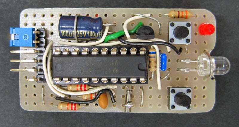
With the LED selected, [Vicente] moved on to building the actual controller. He chose an MSP430 microcontroller for its low power consumption, driving the LED with a watch battery and a transistor. Put together on a piece of protoboard, it’s actually pretty close to a TV-B-Gone. With everything soldered up, it’s good enough to trigger his camera’s shutter from about 5 meters away. Future improvements include cleaning up the code, making the timing more accurate with a crystal, and implementing low power mode on the MSP430.


20€ in local photo store, $3 on ebay.
but those are 100x times less cooler that home build version.
I explain just that at the start of the document.
In the end I think it is cost effective although not for a wide margin.
But this is not the point.
The project is basically for learning and fun.
Wow, what happened to the Euro? Last I checked they were valued at almost twice the US dollar. I thought the author was nuts to think it wasn’t worth it compared to 20€.
How many of us have MSP430s lying around we got with the Launchpad when it came out and never did anything with it? I bet a lot of us could build the whole thing from our junkboxes almost for free. I think the IR LED is the only thing I would have to buy and that only if I am unwilling to just try some random ones of unknown wavelength that i have lying around first. It looks quick and easy too, he did the hard part for us already. If time is money it’s still inexpensive.
Then I looked up the exchange rate. Ok, less than $25 now. i guess if you already have other projects to work on it might not be worh it.. :-( I was excited there for a minute, I thought I saw a good Christmas gift idea for my wife!
Unless you last looked 6-7 years ago, you still would have only found the EUR to be worth $1.60.
Some Bushes have a knack for doing things like that.
Nice, but since he now has all IR-remote hardware he can also add codes for Nikon, Olympus, Pentax and Sony to make this remote even more universal.
“The total power emitted by an IR LED is usually a function of its beamwidth”
err… no.
Ok, true.
The total power emited / solid angle is a function of its beamwidth.
I will correct it in the blog. Thanks
As you have used quoyes in your comment:
“The total power emitted by an IR LED is usually a function of its beamwidth”
I expected to find the quoted text in my document but I cannot find it.
Can you please giveme the location of this sentence.
Hi Vic,
that’s a quote from the HaD article, not from your blog. Second paragraph, second sentence. I’m sorry for that miscommunication!
@HaD should fix it though.
Ben
Ok, understood.
In any case, my blog included a phrase “In every radiant emitter there is a compromise between angle and power. ” I have changed it to “In every radiant emitter there is a compromise between angle and power density.”
Your comment helped me to rewrite a potentially misleading sentence.
My HTC One can’t do much but it can do this :>
All of my consumer DSLR’s and “Prosumer” models have a jack on it for a shutter release. Even the Canon Rebel XT had a 2.5mm stereo plug hole for a Shutter release.
Sure, but it is not a practical solution for a 5m distance.
I have built several cable releases myself. Worked great for bulb mode.
Perhaps someday I will build an intervalometer, but that will be another project.
Nice work! You should consider move the transistor load (i.e. the led plus resistor) from emitter to collector. Then you’ll be able to properly saturate the transistor and hence get more output power.
That is explained in the blog.
Saturating the transistor reduces the conmutation speed (turn off time is longer) and don’t give more output.
The forward voltage of the LED is 1.6V máximum at 100mA. Giving more voltage to the LED would damage it in the long term.
That’s why emiter follower configuration is used. It gives 3V-0.7V = 2.3V voltage swing.
As we cannot use the full 3V swing, we eliminate the base resistor, reduce the switch time and augment the efficiency as no base current is wasted to support unknown forward beta gain.
If you want to increase current (probably damaging the LED in the long term) you can always remove the 6.8Ohm limiting resistor.
Interesting project but it doesn’t seem like it is really using the msp430 low power or timer features to their fullest capabilities . Check out the code in the post below. It doesn’t require an external XTAL and it runs on a msp430g2231. You can re-purpose the IR led from a Dollar Tree remote.
http://forum.43oh.com/topic/2254-pronto-ir-code-transmission/
Off course it does’t use currently any of that.
In fact, with its current firmware, it doesn’t use the XTAL at all.
You can remove the two 22k resistors and the XTAL and it wil work just fine.
If you don’t need to ISP program it, you can also remove the 47k resistor (shorting it) and the 1nF capacitor together with the ISP connector.
The project is planned as a development platform for future firmwares.
The current first firmware is developed in Energia and is a quick and dirty solution.
As is explaned at the end of the blog entry in the future I plan to:
* Develop the firmware using my Eclipse MSP GCC toolchain
* Implement the MSP430 low power mode so that the jumper can always be in ON mode
* Use the 32768Hz crystal to provide a more robust timing
* Implement the low battery indication using the resistors connected to P1.6 and P1.7
The Energia firmware was to test the system so I can build de the hardware and leave the rest of the work only on the software side of things.
Is the source code for this project available?
Yes, its linked in the blog entry:
https://docs.google.com/document/d/1rqWkRUU4eEmcjEnAVqccBHkRR-vANMMnUwILBC5ER6o/edit?pli=1
But it is only a first firmware written in a few minutes using Energia.
Energia gives Arduino like easy coding for MSP430 MCUs without needing any damm bootloader. The code can, if needed, be hardware debuged under CCS. It gives confidence that the hardware is running properly in no time.
Next firware will be developed in MSP GCC using and Eclipse environment.
I plan to include all the low power bells and whistles on the next firmware.
Eeew Energia, :-D.
Not using low power mode is probably going to cause the MCU to use up more power over this thing’s life than the LED (~300mA) if you leave it looping like that. If you put the chip right into LPM4 and wake via the port1 vector (where both your buttons are) you’ll get this down to ~100uA!!
Here’s the GCC function you want:
__attribute__((interrupt(PORT1_VECTOR))) void Port1ServiceRoutine(void) {
/* Check what button was pressed here, both buttons will start this function */
button_pressed = P1IFG;
/* Clear the interrupt flag NOW, it must be done before you exit this function or you will just immediately interrupt on PORT1_VECTOR again. It’s good to do it at the top because it allows you to catch the other buttons being pressed while you process for the first one. */
P1IFG = 0;
/* now do your stuff */
do_stuff();
}
Yeah, I know.
As I already said. The first firmware is quick and dirty.
Energia is great for that ;-)
I will use GCC in the next firmware.
In my case the code will be something like:
// Port 1 RSI
// Called when the SWITCHES are activated on falling edge
interrupt(PORT1_VECTOR) PORT1_ISR(void)
{
// SWITCH1 falling edge interrupt
if (P1IFG&SWITCH1) // Was the SWITCH1?
{
RESET_FLAG(P1IFG,SWITCH1); // Clear Interrupt Flag
flags|=SWITCH1;
}
// SWITCH2 falling edge interrupt
if (P1IFG&SWITCH2) // Was the SWITCH2?
{
RESET_FLAG(P1IFG,SWITCH2); // Clear Interrupt Flag
flags|=SWITCH2;
}
// Get out of low power mode
LPM4_EXIT;
}
It can be optimized but you can get the idea.
I will enter in low power mode in the main loop.
The pushbuttons ISR will just leave low power mode and leave all the processing to the main loop. I don’t like processing on interrupts.
When the main loop ends its operation, it will return to low power LPM4