A two picture montage with the left montage showing a pair of hands holding an assembled and closed turbidity sensor and the right picture showing A pair of hands holding the screw on cap for the turbidity sensor and a prototype board against a backdrop of green leave

Rapid Prototyping To Measure Turbidity In Rapids

[RiverTechJess] is in the process of getting a PhD in environmental engineering and has devoted a chapter to creating a turbidity sensor for river network monitoring. Environmental sensing benefits from being able to measure accurately and frequently, so providing low cost devices helps get more data and excuse the occasional device loss that’s bound to happen when deploying electronics out in the wild. Towards this end, [RiverTechJess] has created a low cost turbidity sensor that rivals the more expensive alternatives in cost and accuracy.

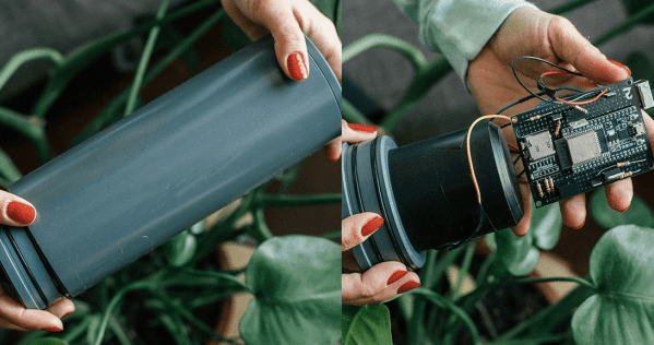
The turbidity sensor is designed to be at least partially submerged allowing for the LED and light sensors to be be able to take measurements. [RiverTechJess] has made a 3D printed prototype to test the design, allowing for rapid experimentation and deployment of the sensors to work out issues. The 3D printed enclosure prototype uses rubber o-rings and “vacuum grease” to provide a watertight seal. An ESP32 microcontroller is used to store logged data on an SD card and drive the TSHG6200 850nm infrared LED and the two TSL237S-LF sensors.

The resulting paper on the turbidity sensor, in addition to the blogs of the process, provide a wealth of data that show what goes into developing and calibrating a device that is meant to be used for environmental monitoring. All source code is available on GitHub and development continues on a newer revision of the turbidity sensor with updated electronics and hardware.

We’re no strangers to water sensors and we’ve seen devices from internet connected water pollution monitors to small handheld potable water detectors.

Video after the break!

Continue reading “Rapid Prototyping To Measure Turbidity In Rapids”

An optical keyboard that works using IR LEDs and phototransistors.

Take A Look At This Optical Keyboard

Making keyboards is easy, right? Just wire up a bunch of switches matrix-style to a microcontroller, slap some QMK and a set of keycaps on there and you’re good to go. Well, yeah, that might work for cushier environments like home offices and Hackaday dungeons, but what if you need to give input under water, in a volatile area, or anywhere else you’d have to forego the clacking for something hermetically sealed? Mechanical switches can only take you so far — at some point, you have to go optical.

the layers of an optical keyboardThis gorgeous keyboard works with reflected IR beams to determine when a finger is occupying a given key site (because what else are you going to call them?). Each key site has an IR LED and a phototransistor and it works via break-beam.

[BenKoning] wanted a solution that would be easy for others to build, with a low-cost BOM and minimal software processing cost. It just so happens to be extremely good-looking, as well.

The reason you can’t see the guts is that black layer — it passes infrared light, but is black to the eye. The frosted layer diffuses the beams until a finger is close enough to register. Check it out in action after the break, and then feed your optical key switch cravings with our own [Bob Baddeley]’s in-depth exploration of them.

Continue reading “Take A Look At This Optical Keyboard”

Using A Vending Machine Bill Acceptor With Arduino

We’ve all seen, and occasionally wrestled with, bill acceptors like the one [Another Maker] recently liberated from an arcade machine. But have you ever had one apart to see how it works? If not, the video after the break is an interesting peak into how this ubiquitous piece of hardware tells the difference between a real bill and a piece of paper.

But [Another Maker] goes a bit farther than just showing the internals of the device. He also went through the trouble of figuring out how to talk to it with an Arduino, which makes all sorts of money-grabbing projects possible. Even if collecting paper money isn’t your kind of thing, it’s still interesting to see how this gadget works on a hardware and software level.

As explained in the video, a set of belts are used to pull the bill past an array of IR LEDs. The hardware uses these to scan the bill and perform some dark magic to determine if it’s a genuine piece of currency. [Another Maker] notes that these readers actually need to receive occasional firmware updates to take into account new bill designs. In fact, the particular unit he has is so out of date that it won’t accept modern $5 bills; which may explain how he got it for free in the first place.

Years ago we saw one of these bill acceptors used to make a DIY Bitcoin ATM. Of course back then, a few bucks would get you a semi-reasonable amount of BTC. These days you would skip the paper currency and do it all digitally.

Continue reading “Using A Vending Machine Bill Acceptor With Arduino”

Playing Jedi Mind-Tricks On Your TV

Gesture-enabled controls mean you get to live out your fantasy of wielding force powers. It does, however, take a bit of hacking to make that possible. Directly from the team at [circuito.io] comes a hand gesture controller for Jedi mind-trick manipulation of your devices!

The star of the show here is the APDS-9960 RGB and gesture sensor, with an Arduino Pro Mini 328 doing the thinking and an IR transmitter LED putting that to good use. The Arduino Sketch is a chimera of two code examples for IR LEDs and the gesture sensor — courtesy of the always estimable Ken Shirriff, and SparkFun respectively.

Of course, you can have the output trigger different devices, but since this particular build is meant to control a TV the team had to use a separate Arduino and IR receiver to discover the codes for the commands they wanted  to use. Once they were added to the Sketch, moving your hand above the sensor in X, Y or Z-axes executes the command. Voila! — Jedi powers.

Continue reading “Playing Jedi Mind-Tricks On Your TV”

DIY Multi-Touch All The Surfaces

Ever wanted to build a touch table or other touch-input project, but got stuck figuring out the ‘touch’ part? [Jean Perardel] has your back with his multi-touch frame over on IO that makes any surface touch-reactive. In [Jean]’s case, that surface is ultimately a TV inside of a table.

Of course, it’s a bit of a misnomer to say the surface itself becomes touch-reactive. What’s really happening here is that [Jean] is using light triangulation to detect shadows and determine the coordinates of the shadow-casting object. Many barcode scanners and consumer-level document scanners use a contact image sensor (CIS) to detect objects in the path of IR LEDs. These are a low-power, lower-resolution alternative to the CCDs found in high-grade scanners.

As [Jean] explains in the video below, an object placed in the path of a single IR LED facing a sensor array of either type will block the light from reaching the sensors. Keep adding LEDs and their emission angles will begin to overlap, increasing the detection precision. [Jean] reverse engineered a couple of different types of scanners until he found a suitable one. He ended up with CIS that has 2700 light sensors lined up in the space of 20cm (7.87″).

[Jean] designed a 3D-printable frame to hold 96 IR LEDs in stacks of three. A Teensy turns on the LEDs, detects the touch event, calculates the position, and sends those coordinates to a Pi to be displayed on the screen. He eventually went wireless and then built a nice looking touch table to house a 32″ TV.

This is not the only way to build a multi-touch table, nor is it the simplest. Here’s one that uses finger presses to scatter light and an industrial strength projection-based table that was open-sourced a few years ago.

Continue reading “DIY Multi-Touch All The Surfaces”

How To Eclipse When All You Have Is A Welding Helmet

What do you do if you don’t trust cheap eclipse-watching glasses from the internet? What about if everyone’s sold out? Well, if you want to watch the eclipse and you have an auto-darkening welding helmet, you can do what [daniel_reetz] did and hack something together with a remote and your welding helmet to let you see the eclipse without blinding yourself.

Essentially, the hack tricks the helmet’s sensors into thinking it’s very bright. [Daniel_reetz] accomplishes this by gluing a remote with an infrared LED to the side of the helmet and covering it with a 50mm plastic lid. There are two sensors on [daniel_reetz]’s helmet, so he covers the other one with aluminum tape. What this means is that when he presses a button on the remote, the lid-covered sensor thinks it’s very bright out and since the other sensor is covered, it darkens the lens of the mask.

I’m sure some of our readers could come up with a more sophisticated method that would allow you to do something other with your hand than press the remote buttons, but this is a quick and easy hack that’ll get you able to take a quick look at the eclipse – assuming you have a welding mask capable of shading to level 13 or 14. If you are hoping to catch a glimpse of the eclipse, check out the safety guide from NASA just to make sure your eyes are safe. For another method of viewing the eclipse, check out this wearable pinhole camera. For another welding mask hack, check out this augmented reality mask.

Continue reading “How To Eclipse When All You Have Is A Welding Helmet”

Hackaday Prize Entry: Open-source Pulse Oximetry

Chances are pretty good you’ve had a glowing probe clipped to your fingertip or earlobe in some clinic or doctor’s office. If you have, then you’re familiar with pulse oximetry, a cheap and non-invasive test that’s intended to measure how much oxygen your blood is carrying, with the bonus of an accurate count of your pulse rate. You can run down to the local drug store or big box and get a fingertip pulse oximeter for about $25USD, but if you want to learn more about photoplethysmography (PPG), [Rajendra Bhatt]’s open-source pulse oximeter might be a better choice.

PPG is based on the fact that oxygenated and deoxygenated hemoglobin have different optical characteristics. A simple probe with an LED floods your fingertip with IR light, and a photodiode reads the amount of light reflected by the hemoglobin. [Rajendra]’s Easy Pulse Plugin receives and amplifies the signal from the probe and sends it to a header, suitable for Arduino consumption. What you do with the signal from there is up to you – light an LED in time with your heartbeat, plot oxygen saturation as a function of time, or drive a display to show the current pulse and saturation.

We’ve seen some pretty slick DIY pulse oximeters before, and some with a decidedly home-brew feel, but this seems like a good balance between sophisticated design and open source hackability. And don’t forget that IR LEDs can be used for other non-invasive diagnostics too.

The 2015 Hackaday Prize is sponsored by: