Welcome back to this week’s installment of Scope Noob where I’m sharing my experiences learning to use my first oscilloscope. Last week I started out measuring mains frequency using an AC-AC wall wart adapter. Homework, for those following along, was to build a bridge rectifier and probe the signals from it. Let’s take a look.
Bridge or Full-Wave Rectification
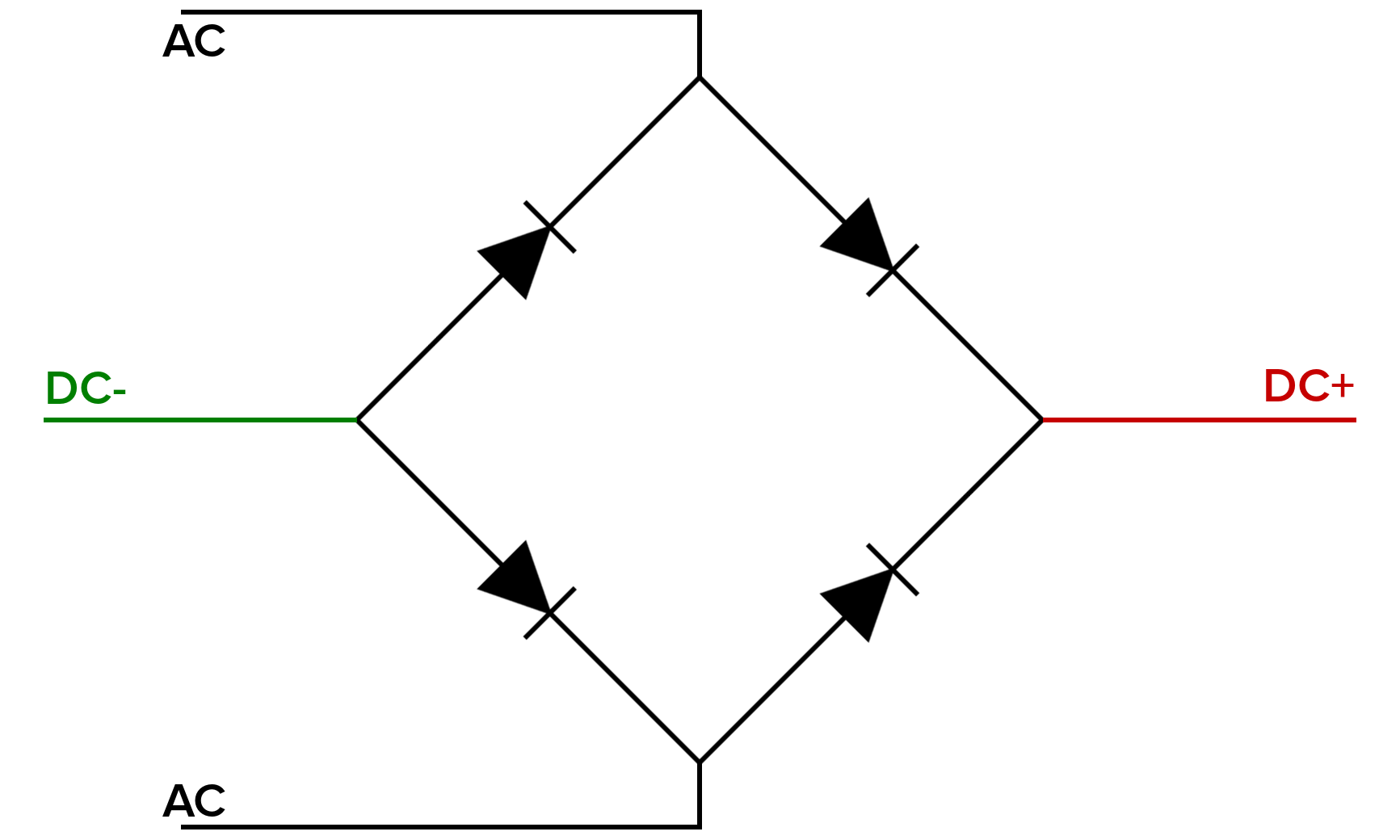 To the left is a schematic of a full-wave rectifier. Again, the important thing to note is that I’m using a 2-prong “wall wart” AC-AC adapter that converts the 120V line voltage down to 12V. Because of this I’ve used 1N4001 diodes to make the bridge rectifier.
Bridge rectifiers are also known as full-wave rectifiers because they take the alternating current and use both parts of the waveform to generate a direct current. A full explanation is not the purpose of this column so check out resources like this tutorial on the top (link dead, try Internet Archive) for the theory and math behind the concept.
 I made a video of these measurements which is embedded above. I started by again probing my incoming AC waveform to make sure that I had a known starting point. This time I used “AC” as the trigger source which is found by pressing the menu button on the trigger part of the scope. This uses the mains signal powering the scope to trigger the measurements which is quite handy for this particular exercise.
But when I went to probe the rectified waveform I was met with a surprise. My full-wave rectified signal was only showing up as half-wave rectified on the scope. The screenshot to the right shows an upward curve followed by a flat area where in there should have been continual arcs.
You Can’t Probe Everything at Once


It only took me a few moments of head-scratching to figure this one out. With a reference-clip from both probes (channel 1 and 2) connected I’m actually shunting around one of the diodes, effectively turning the bridge back into a half-wave rectifier. That’s because, as I talked about last week, the reference clips for all of the channels on the scope are connected to each other and to the ground pin on the scope’s power cord.
Disconnecting channel one from the AC measurement resulted in the full-wave rectified signal I was anticipating. But here’s a question I need help answering: Why is every-other waveform transition a bit mangled? I had expected a consistent waveform through every transition.
Smoothing and Regulating

To complete this set of tests I added an electrolytic capacitor to the DC connections to smooth the output. This cap is both under and over spec’d at the same time, being 3300uF but only 10V. It’s a cap I pulled off of an old motherboard and was floating loose in the same container as some of my jumper wires.
The image above shows the regulated power rail on channel 1 (yellow) and the smoothed DC rail on channel 2 (blue). The 7805 is putting out 5.79V according to these measurements. When I was making the video I was puzzled because I thought the smoothed signal was a higher voltage than without the capacitor. Looking at the screenshots now I realize that isn’t the case. I think this is an important lesson as well. Take screenshots as you’re troubleshooting a circuit so that you can double-check the values you thought your remembered!
Homework
 I’ve already done a bit of work on next week’s column and I’m super excited to share all the things I’ve learned. Here’s a little taste of the good stuff. I should be seeing just one sine wave on the scope but I’m getting two of them. I also delighted in finding a hiccup in the signal and using that to track down the cause in my code.
Give this a try yourself this week. I’m using Direct Digital Synthesis by driving an R/2R ladder using a microcontroller. I was inspired to take this on by [Bil Herd’s] in-depth explanation of the topic. If you use a microcontroller as I have, I encourage you to split the eight digital outputs between two ports of the microcontroller and see what happens. I’ll cover this and more next week!
I also need help with suggestions for future Scope Noob topics so let me know what you think I should try by leaving a comment below.


Be wary when doing high power projects. The bench power supply I was using ties DC ground to ac ground. I found that out only because the power supply’s internal relays clacked when it shouldn’t of.
It’s “shouldn’t’ve” or “shouldn’t have” and has nothing to do with the word “of”…
http://public.wsu.edu/~brians/errors/couldof.html
The great thing about comments correcting the grammar of other comments is at least one of the comments isn’t about grammar.
My grammer always used to give me a slap if I taught her to suck eggs. Nice article. Edyoucayshunal init. :)
LOL @ “shouldn’t’ve”,
1) Should not have
2) Shouldn’t have
You can’t post-pend two abbreviations to the same word in English. Well, as far as I know!
It’s a blog comment not Proceedings of the IEEE. People write how they talk.
IEEE proceedings ain’t exackly great Inglish neither.
Yep they do. I’m Douglas Joseph, to my grandma I was dougie joe. She was taught to pronounce words phonetically to spell them However with her Germans from Russia living in Kansas accent she wrote my name as dukyjo. Well at leest she created for me an anonymous internet name to use :)
is the short form of aint it init, innit or inuit?
Get off my foc’s’le! (Alternative spelling of forcastle).
Yes you can. For example: “y’all’dn’t’ve” = “you all (c|sh|w)ould not have”. Source: I read an explanation of this written by a Texan.
Shouldn’t’ve is a real word.
Couldn’t’ve is, also.
Maybe try with a load to get rid of the mangle, I don’t get why it’s only happening half the time. Also you better use the right voltage for your caps or they’ll fail (from your screenshot, you need a minimum of 18.2V and you better leave a margin, so at least a 20V cap)
Rectified AC voltages have twice the frequency of the original AC. The ‘effect’ you see is because the ‘distortion’ of the original AC is at the same frequency as the mains voltage. So it will be the result of a synchronous load such as light dimmers, ceiling fan controllers or a large inductive synchronous motor like a fridge compressor.
You would commonly expect to see such a significant distortion from a switch mode power supply but not a transformer.
The magnetic fields of a transformer cannot be forced to change their ‘rate of change’ very easily without a significant load. For this reason what your seeing here is an indication of a loading problem in the building where these tests were made.
The use of a transformer wall wart is ideal for this procedure as it is effectively a double insulated device, meaning there is no ‘earth’ or ‘ground’ on the secondary side. Switch Mode Power supplies however have many different configurations some of which can result in damage to the PSU or scope when the scopes earth lead is connected to a test point that it not at earth voltage.
I don’t know the mains system where these tests have been done but if it were here where we have a multiple earth neutral (MEN) system then I would be asking questions about what may be causing this distortion as it cold potentially be dangerous.
Where I am the mains voltage is 240 Volts so it is not at all as forgiving as the lower voltage systems such as 110 Volts. If you have a situation where you receive a substantial shock from 110 Volts then in the same situation in a 240 Volt system you would be dead. That’s not to say 110 Votls can’t kill you because it most certainly can.
Hello,
Perhaps a bit off topic. I am in my initial practice of electronics. If the goal is to determine the digital voltage value from the rectified AC signal and the digital value is to represent the DC value, is the digital value determined by getting to the Vrms of the rectified signal or the peak? I can see how rectification works. I can see how peak detection works. I can see I would want peak detection if I wanted to know the biggest voltage peak. But what if I want to determine the voltage represented by the rectifier. Should that be some kind of averaging of the half waves? Thank you.
The digital value from your DMM is dependent on how the DMM does it calculation. The good ones has a RMS chip, so they would give you the RMS values.
The cheap ones just give you an average based on certain assumptions on the waveform. If your waveform does not match that assumption, then the values would be bad because the multiplier is wrong. Also if the waveform is distorted and have different duty cycles, then the numbers would be different.
See here for how the average value related to the RMS for different types of waveforms: en.wikipedia.org/wiki/Crest_factor
To expand on that, most cheap multimeters will only give you an accurate rms voltage of an AC signal if it is a pure sine wave. Calculating the rms voltage of a changing ac waveform is more complicated, voltmeters that can do it are usually labeled as “TrueRMS” or something similar.
Thank you John. I am assuming a main reason the Vrms is interesting is when the waveforms are different. For example, a sinusoidal, square, triangle waveform may all have the same amplitude. But the Vrms is different. If that is true, is the “non-true” Vrms reading on a DMM useful?
If you know the crest factor you are dealing with, then you can scale the non-RMS meter reading to get an approximation of what the RMS voltage should be. I am assuming that you haven’t read my wiki link.
Here it is again for the URL: http://en.wikipedia.org/wiki/Crest_factor
Hey Mike,
So if the mangled portion is only happening half the time (and every other half-wave?) perhaps that means one of the diodes is to blame. Perhaps swap the two AC input power wires and see if it happens on the other half of the wave?
Triggering at the same spot you should be able to determine if that’s the case.
My first thoughts too, along with maybe some ringing or capacitance along some of the extra leads on the board
Instead of just guessing, we should use this as a learning experience to understand what we see on the screen.
On that half of the wave, it looks like the voltage is not dropping all the way. What would cause voltage to not drop? Capacitor would hold a charge. Or, the pattern is starting to simulate the pattern when the diode was jumpered by the ground clips. This is what makes me think a bad diode.
The “other half of the wave”? How can you tell which is which once you’ve turned the power off and on again?
Many scopes, including the one in the subject of this thread, have an option to use the AC power line as the trigger source. You don’t need to connect a probe to it; the scope has the connection pre-wired inside the scope itself. You just select the AC line as your trigger source, ask it to trigger as the line rises through zero volts, and then your waveforms will be locked in a consistent position relative to the power line. One half of the rectified wave happens in the first 1/120s after the trigger, and the second half of the wave happens in the second 1/120s after the trigger.
Ideas for Scope Noob:
– Measuring things:
* Time: Pump a square wave through a series resistor into a load and show how to measure the rise and fall-times.
* Current. Use two probes to measure the voltage on both sides of a high-side small resistor going to a load. Show how to subtract the voltages and calculate how much current is going into the load. (Have the load do different things and show how to see the max and min current consumed.) (Make the load an Arduino or something.)
* Frequency: Make a somewhat-periodic signal (Maybe a pulse train from a microcontroller) and show how to measure the frequency of certain events. (1/Time, but show us.)
I like your suggestions
BTW It would also be nice to see a companion tutorial on Spice (e.g. LTSpice) to show the same circuit under simulation. The fun part is to show how close the simulated waveforms to the measured one. Even a disagreement would be interesting if you cover why there are differences.
This way for reader without scopes would be able to wire up circuits and see waveforms under what-if. It is very useful for designing analog circuits and have a good confidence of it working before you prototype.
Thanks for doing this series!
Thanks for the series, Mike. As a scope n00b myself (currently playing with an old analog scope, and hoping to get a digital one soon), I find this very helpful.
To the community at large: has anyone used the B&K 2190D scope? I am thinking of picking one up, but it seems quite new and I can’t find any real reviews on it. See http://www.bkprecision.com/products/oscilloscopes/2190D-100-mhz-1-gsa-s-2-ch-digital-storage-oscilloscope.html for the product page. (I would much rather go with the Rigol DS1054Z, but they unfortunately don’t carry them at Mouser). Specs seem good (only limitation is 2 Ch vs 4 Ch, but I think that 2 is enough for my purposes).
Cheers
Findchips search returns Allied Electronics has that Rigol model in their catalog for $399, but not in stock. I guess you can try ordering from them.
Try here for the DS1054Z:
http://www.saelig.com/PSBE1004/PSBE1004010.htm
Thanks for the replies… long story short, I am stuck with sourcing through Mouser for this. I asked them if they could order one, but I guess they are not an authorized Rigol distributor. Too bad :-(
Hence, I am looking for feedback on alternatives which *are* available at Mouser. Of the various options, there is this B&K one, and Tektronix ones at 50% more cost with lower bandwidth. I guess a big part of my question is whether spending more on a Tektronix scope is worthwhile, given the lower specs.
Cheers
For a starter scope, no need to pay the Tek premium, unless you’re digging in purposefully with the intent to make a career out of your interests, in which case it would depend on your budget. Truth be told, even if that were the case, I’d personally still buy the less expensive scope and use the money I saved to buy a good set of probes.
Tek makes some fine products for professionals/industrial usage, don’t get me wrong. They’ve earned their reputation. That said, for hobby/starter use, there’s no reason to buy a Bugatti when all you need is a Ford.
Also consider the bandwidth you need (or might need). High BW scopes look sexy on paper, but if all you’re probing are audio or control circuits, then high BW is overkill for you.
Thanks for the comments. I am a programmer by trade, and I don’t foresee electronics ever becoming more than a hobby, so that makes sense.
As for bandwidth, I’m sure 100MHz is more than I need now (honestly 10MHz is probably more than I need now). I just want to walk the fine line between not overbuying and not buying something that will need replacing in 5 years. I want this scope to last a lifetime. (Not sure how feasible that is these days…. I know a good analog scope could last 30+ years; I think my current analog one was made in the 70s, but now nothing is made to last…)
Anyway, thanks… I think the one I am looking at is probably a good bet. It’s pretty much as inexpensive as you can get for a non-USB scope, but hopefully will do enough that I can grow with it.
Cheers
I’d recommend 32 MHz, so you can measure a 16MHz Atmel 384P chip (inside Arduino).
It is a bit more complicated than just doubling the sampling rate. Nyquist theory basically boils down to needing have at least 2 points to fit a pure sine wave. You would need a lot more information for dealing with something that have harmonics. There are rules of thumbs about 3rd or even 5th harmonics.
There are app. notes to tell you that how much error you can expect for a rise/fall time measurements based on bandwidth. tl;dr more is better.
BTW you are confusing sampling rate vs bandwidth. They are two different things especially on a digital sampling scope where they use undersampling techniques for sampling repetitive waveforms that are outside what the scope can do for real time.
Bandwidth is how much of the upper harmonics that your scope can see. Think FFT and how that upper harmonics can affect the shape of the waveforms you are seeing.
http://www.eetimes.com/document.asp?doc_id=1276244 “Choosing an Oscilloscope with the Right Bandwidth”
>As a rule of thumb, your scope’s bandwidth should be at least five times higher than the fastest digital clock rate in your system under test.
>All fast edges have an infinite spectrum of frequency components. However, there is an inflection (or “knee”) in the frequency spectrum of fast edges where frequency components higher than fknee are insignificant in determining the shape of the signal. To calculate fknee:
fknee=0.5/RT (10-90 percent)
fknee=0.4/RT (20-80 percent)
Yeah. Buy the best probes you can afford and learn to use the scope & probes correctly. They can affect your measurements.
BTW even iif you are not using a Tek, you can always read Tek’s and other brand name vendor’s app. notes on how to do measurements correctly.
Hmm, I am looking a bit deeper at what the various scopes can do… and a huge problem with both the Tek and B&K ones I am looking at are the sample memory. The Rigol DS1054z has *much* deeper memory: 12 *million* samples total vs 40k samples total on the B&K and 2.5k samples (per channel, so 5k total) on the Tek. That is a huge difference, and I think would make a real world difference for me (much more than bandwidth).
I don’t know… I may have to just hold off and see if I can’t get the Rigol, by hook or by crook ;-)
Thanks to all for your replies.
Long memory is useful if you need to find out what’s going on before/after a trigger especially a rare event. Say something glitches on your signal and you want to know if there was something wrong with the power or something else.
If the event is more frequent, then you play with some fancy trigger delay etc on the scopes and live with the shorter samples. I have never learnt it and most people would simply use a long sample. Long samples might mean long delay when you scroll the waveforms, but you have the option of using a shorter sample size instead of wishing for more.
Somewhat related, long memory is very useful for debugging or reverse engineering data communications. Hook your oscilloscope to an IR phototransistor and figure out what data your TV remote control is sending to a TV. Hook a couple of probes on the send and receive lines of an RS-232 device, and monitor the bidirectional communications. There are lots of other examples. Once you capture a long waveform, you can dump it to a csv file and process it in your favorite programming tool or even spreadsheet.
There are other devices custom made for this sort of task — things like a logic analyzer or bus pirate. But if you’ve already got a scope with long enough memory, you may be able to use it for the task and save buying another tool.
Actually I used a logic analyzer to look at the IR protocol to my xbox and new TV. I use that info to program my “One-For-All” remote (google that). It has programmable protocols – carrier frequency, bit formats for ‘0’ & ‘1’, binding raw data to the keys. I even found out why my xbox remote clone wasn’t getting a good signal – fixed that by playing with the On/Off duty cycle.
I like the way the scope presents the measurements. I guess that Mike still haven’t learnt to use (CH1-CH2) diff measurement from last time? The Invert [Off] is option there on the right hand side so that you can do Ch1 + Ch2 (INV) = Ch1-Ch2.
First… Your measurement of the rectified waveform is distorted because you have no load on the rectifier DC output. If you put a resistor (~10K), and your scope probe, across the DC+ and DC- output (Scope GND to DC-), you should see a true rectified full wave waveform (120Hz) of the original 60Hz. This is due to the diode pairs conducting in the positive, and negative portions of the incoming 60Hz waveform, resulting in nothing but twin positive transitioning half waves.
Second… When you plug the capacitor in, you still have almost no load, and you saw approximately 1.414*12, or 16.97 volts, and is exactly where it should be. This unregulated voltage will remain high until you reach capacitance vs load timing, at which time you will start seeing lower voltage, and 120Hz ripple.
Was about to chime in in a similar vain to the above, you need to load up the DC output of the rectifier a little, the scope represents a 1Mohm load but sometimes I find circuits dont quite behave untill you put a greater (but still modest) load on them.
By accidentally shorting one of the diodes (by placing the two scope clips on different nodes), you’ve effectively connected one diode (top left) directly across the AC input. This poor diode will be shorting the AC input on alternate half cycles, and is probably now dead. This might explain the distorted waveform.
as an aside, I consider it good practice to only connect one ground, bit like working on high voltage woth one hand behind your back, saves you making an accidental mistake.
Also beware of hidden ground connections – most modern scopes grounded their input to Earth Ground on their power cord.
Isolation transformers are your friend.
Connecting only one ground will work with slow enough signals (and these 60Hz/120Hz signals in this example are certainly slow enough), but when dealing with faster signals, each probe needs a ground connection as close as possible to the probing point. At high enough frequencies, even the short ~5 cm grounding lead is too long — its inductance becomes nontrivial. That’s why the probes typically come with very short grounding spring clips.
Out of curiosity, what sort of frequencies are we talking about? How fast is too fast to use a single ground lead? (Obviously the specifics will vary, but I would be interested in a rough ballpark estimate).
As a very rough oversimplified ballpark, if you’re dealing in Hz, it doesn’t matter much. If you’re dealing in kHz, you probably want to at least make sure each probe has its own ground connection. If you’re dealing in MHz, you probably want to consider using a short spring or similar coupling instead of a wire ground lead of a few inches long.
Here are some links exploring the issues.
https://www.youtube.com/watch?v=zodpCuxwn_o
http://www.linear.com/solutions/4450
http://teledynelecroy.com/doc/passive-probe-ground-lead-effects
“Take screenshots as you’re troubleshooting a circuit so that you can double-check the values you thought your remembered!”
Sure – lemme just break out the polaroid camera for my scope here…
http://upload.wikimedia.org/wikipedia/commons/1/1f/Tektronix_C-5A_camera.jpg
Dang, that brings back memories. Now I feel old.
Looks like a fun learning experience! Keep at it :)
Another fun thing would be looking at Lissajous curves and phase difference between two signals. :)
“DON’T FLOAT THE GROUND” should be a scope measurement rule, unless you have isolated probes meant for doing that (as well as knowing what you are doing). You can ruin a scope input channel, as well as circuit components. Yes, you can use an isolating transformer. Even with an isolating transformer, you may still use cause the scope probe grounds to short across your circuit being measured, as your drawing above shows. You can keep the probe references on the circuit ground, where they belong, and use the scope math functions to calculate the difference between the two probes. Tektronix has guides to making floating measurements, as well as all sorts of other measurement information online.
Hey, on occasion I get a 404 website error when I browse this page. Just a heads up, regards