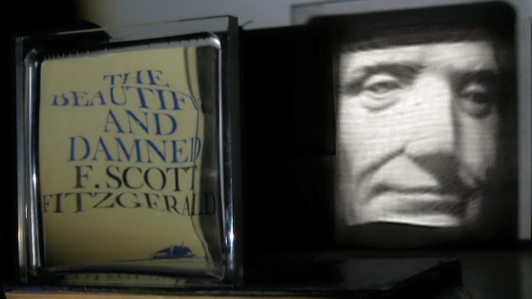
Lumographic images are those patterns you see at the bottom of swimming pools. When water works as a lens, the light patterns of bright and dark are random and wandering based on the waves above. [Matthew] figured out a way to create fixed images from lens shape alone. The images only morph into view clearly when light shines at the proper angle. At near angles an eerie fun-house mirror effect appears, but too far off and it scatters unrecognisably.
The exact method for designing the optics is not explained, though we are sure someone in our readership could figure it out. The artist claims it to be a hundred year old million-variable math problem. The lenses are often quite thick and do not resemble much of anything. The effect however, is sharp, clear and detailed.
At first he suspected he needed astronomically-expensive military-grade 50 nanometer (0.000002″) precision machining for the lenses, but some friends in the autobody industry gave him a few tips to squeeze good enough accuracy from more affordable industrial machines. The technique also allows for images to appear from mirrors and internal reflections. It is probably not something you can 3D print or machine yourself, but it would be interesting to see someone try.
[Matthew]’s work is on display in the “Composite” gallery at the National Museum of Math in New York (MoMath). See the video after the break for a peak at the machinery he uses to manipulate the lenses to enhance the visuals in the exhibit.


Whoa… that’s trippy! Love it!
Looks like a technique like this: http://people.csail.mit.edu/wojciech/GBC/gbc.pdf
Lots of recent work in the area – disappointing that the artist doesn’t acknowledge.
Had to go to the internet archive to find information on specular holography methods – the current page has images missing or deleted, though the text gives an idea of how he’s doing it:
http://www.zintaglio.com/how.html
Specular holography: http://web.archive.org/web/20140524121918/http://www.zintaglio.com/how.html
He published a paper on Specular Holography on Arxiv a few years back that goes into more detail: http://arxiv.org/abs/1101.0301
The theory behind his specular holography is similar to that of scratch holograms.
lots of images, presentations, etc.
http://lgg.epfl.ch/caustics/
The “how” page has broken images – one would hope that he puts them back but otherwise it seems to refer to using standard bodyworking materials for lens construction/casting.
Also, from the Internet Archives, some information about other work:
http://web.archive.org/web/20131206123526/http://zintaglio.com/how.html
I really like the example that focuses different colors into different image components.
Isn’t he just making “lenses” so that they make some destructive or additive interferences to make a dark or a clear zone?
So, when he moves the lenses, the point where the interference happens changes, thus creating the distortion.
That would explain the need for a printer, and not just some classic lenses, and also why he is using monochromatic light.
Also, the drawing at the end of the video seems to suggest that.
(sorry if the links above are saying the same thing, I didn’t took time to read all of them).
@plop. This effect is generated by intensity modulation. This mainly means that the light is redirected based on the normal of the surface, which can be generated by crude fabrication means. In electronic terms, the powers are added, ie. this does not consider the phase relations. The video also shows images with white light, which by deinition is not monochromatic. To be able to do interference patterns with monochromatic light you need to be accurate down to at the very minimum 100 nm.
As a side note. When actually considering interference patterns, interesting effects can be achieved by the fact that for a normal lens, the relation between the focal point and the image plane can be described by a 2d-fft.
Yes, white light… true… I should have thought a bit more…
I don’t get the thing with ffts, the diffraction coefficient varies with the wavelength, but except helping calculation with polychromatic light, I don’t understand how it can help.
For the caustics stuff, if I understood correctly, you need to have a part of the light beam that is reflected once on a surface, and then on another, to go back into the first with, this time, an angle allowing them to pass through the surface (if the image is viewed the other side of the “lens”, as with a glass in the sun), but in the research papers in the links, they are using really fat “lenses”. So there can be mostly perpendicular surfaces to allow this maybe?
But the ones the artist is using are thin, maybe it is not the same effect?
And for the need of high precision for interference, there something about that in the article, the artist thought he would have to use an high precision machine, of about 50 nm.
First forget about the fourier transform, it was just another not related to this article.
Thickness has nothing to do with it. Suppose we work with three mirrors, of I align them so that the light coincides at the projection surface, the intensity at that spot will be three times as high, as with one. The ‘lens’ has the same effect in transmission. The thickness has nothing to do with it. Just think of a fresnell lens in these old overhead sheet projectors, this also achieves to redirect the light towards the objectif lens, in lets say 2 mm.
Getting the intensity right is easy, but what area on the ‘lens’ should this intensity come from, This is the whole problem. The normals are easy to calculate. The problem lies in distributing the normals in such a way over the ‘lens’ surface, that it is possible to physically realize this surface.
As for the accuracy: “he SUSPECTED he needed … 50 nanometer … precision”. A typical cnc can go down to 50 um. Then it just needs to be polished to reduce scattering.
50 um (micron) and 50 nm are not the same. Microns are 1000x larger than nanometers. Modern CNC can’t get to 50 nm precision– that’s insanely tight for tolerancing. I may be misreading your point on that, though.
It’s an interesting question of where to pull the light from. I like it as a problem space! I might fiddle with something and see what I can come up with.
Sounds like a use for those printed lenses you featured last week.
You’ll be wanting to read:
http://www.chateaunoir.net/caustics.html (2014 paper)
all out of here (mainly) http://lgg.epfl.ch/caustics/index.php
ceres solver used is in github but no code of the project found.
The patterns seen at the bottom of swimming pools are called “caustics” and not “lumographic images”. (see: http://en.wikipedia.org/wiki/Caustic_%28optics%29 )
The deformed surface of the water forms the caustics by refracting and concentrating the light at different areas. Caustic is a common feature of rendering engines. The rendering process is usually done by tracing and refracting rays from a light source through a transparent surface such as water (backward ray tracing, photo mapping, etc).
The goal here is to invert the computation: finding the deformed surface that produces the wanted caustics. There were two papers at Siggraph 2014 on that subject:
– Poisson-Based Continuous Surface Generation for Goal-Based Caustics
http://nishitalab.org/user/egaku/tog14/absttog14.html
– High-contrast Computational Caustic Design (already cited by neon22)
http://www.chateaunoir.net/caustics.html
The technique described in the later paper produces produce truly remarkable results (much superior to the ones shown in this post).
The following video is a must see:
https://www.youtube.com/watch?v=R00IvqcI9jU
The paper explains how the lens are fabricated (acrylic milled on a CNC and hand polished).
Is there anyone selling these?
reminds me of a chinese magic mirror.
Hi — artist here. Must … resist … temptation … to comment on comments. Well, here goes anyway:
@plop This is purely geometric optics, so the only thing that matters is the shape of the optical surface or surfaces (sometimes I contour both sides).
@had After a lot of tinkering, my CNC process is now accurate down to a few micron; some chemistry & selective polishing gets me below 1um in places; and I’m still working on getting down to wavelength scales on an artist’s budget. BTW, 50um accuracy is unusable for optics.
@Thinkerer Thx — I fixed the broken “how” pages on my website: The holography page is restored at http://www.zintaglio.com/how.html; the lens page, actually a draft for a poster at the gallery, is temporarily at http://www.zintaglio.com/how_lens.html .
@Michael @neon22 Several research groups have taken a crack at the picture-forming lens design problem, and viable approaches have been around since the late 1990s. Interestingly, everyone has a different formulation. My continuous solution happens to predate the discrete approximations in the papers you link to, and it appears to be more general, as are some well-known older solutions they could have cited. However, the math was the easiest part of the game; developing an art-quality fabrication process without access to ultraprecise machines was the real slog. (Of course, to an artist, the quality is never good enough.)
@AntoineC The EPFL videos look great because they use an optimal display condition that isn’t really practical in real-world setups. They have the lens quite close to the wall and far from a high-quality point light source, which makes for very crisp images (note the sharp shadows), but cramped viewing. That’s great for filming a single lens making a 10cm-high image in laboratory conditions, but useless for real-world settings like projecting 25 lenses to 80cm-high images in a gallery with tight space constraints. There, each lens is mounted close to the illuminator (a commodity flashlight), and far from the wall. That way we get magnification to painting-size images, but physical law says the image must be degraded by the etendue of the illuminator. BTW, EPFL’s Prof. Pauly visited for lunch last summer and bemoaned this very issue. He also brought some of his optics. They were beautiful, but given similar lighting and projection conditions, they were clearly not candidates for gallery display. He did, however, instill in me a deep and abiding envy his much higher-end milling machine.
Finally, a hobby horse of mine: there are no caustics involved in making the image. It’s a misnomer. The presence of a caustic would imply that some light rays cross en route to the projection surface, which is not the case in these lenses, nor in shallow water (but you’re right about swimming pool caustics). Many methods, including mine, can be tweaked to allow caustics, but that’s pointlessly sub-optimal; as long as the 2nd law of thermodynamics is still valid, any caustically-formed image in the real world can be made non-caustically with a lens that is as smooth or smoother.
@Nonya-Biz The physicist Michael Berry has a terrific paper on Magic Mirrors. There is a related easter egg in the gallery at MoMath.