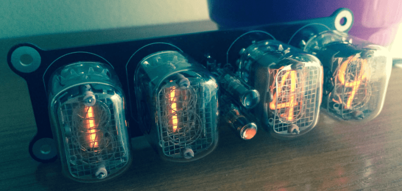
Nixie tubes, while built during the vacuum tube era of the mid-20th century, still exist in a niche among hackers. It’s quite the task to get them up and running due to a number of quirks, so getting an entire clock to work with Nixie tubes is a badge of honor for those who attempt the project. For anyone thinking about trying, [Tomasz] has written an extremely detailed write-up of his Nixie clock which should be able to help.
There is a lot of in-depth theory behind Nixie tubes on [Tomasz]’s page that he covers in the course of describing his clock. As far as the actual project is concerned, this is a simplified design which uses one board for the entire clock, including circuits for the lamps, drivers, microcontroller, power supply, and DC/DC conversion. This accomplishes his goal of making this project as small as possible. The Nixies he chose were IN-12 which are popular in his Eastern European home, but could be sourced from eBay and shipped anywhere in the world.
There is a lot of documentation on the project site, including schematics, microcontroller code, PCB design, and even screenshots of the oscilloscope for various points in the circuit. While this might not be the simplest Nixie clock ever, it is certainly close, more easily readable, and the most detailed build we’ve seen in a while!


The high-side driver construction is bad. Really, really bad. The current is determined only by the 1M resistor and h21e of the transistor. When you make a high-side driver for nixies, a resistor in emitter of the PNPs and better design of the resistive divider is advisable. This way, the driver acts as a current source.
According to the schematic, about 13mA are supplied to each digit 1/4 of time. That means 3,25mA on average. That’s perfectly fine, but other readers may use a different PNP than the KST92 – imagine a transistor with h21e of 300. That would mean 10mA on each digit. Bye, nixies!
You can dial back the voltage if the nixies are too bright. May be sensing the load current from the drivers on ground side and also use that for the feedback loop.
OR PUT THE BLOODY RESISTOR TO EMITTER! It does the same thing and you do not need to do any ground-side sensing.
Even a few kiloohms in collector would make the nixies live longer.
You can certainly use an emitter resistor and make a constant current supply, but not at those voltage divider ratios. You only want a minus few volts on the base.
There are good reasons for using constant current – balancing overall brightness for the different digits.
That is why one should use the transistor in the specs instead of just hoping that a replacement will work properly. Anyone who just slaps in a part without checking the gain or other properties just because it’s the same type of part is just asking for trouble. The design obviously works as it should. If changes are to be made, research and necessary adjustments need to be made before implementing those changes.
I happen to be the author of this project, and yes, you are correct. I would be very unwise to connect the anodes directly to pnp transistor with no current limiting resistor especially for devices that present hysteresis-like behavior (here due to neon ignition voltage)
I’ve even placed such resistors on the schematic (on the collector side) but labeled them as 0 Ohms just because I didn’t know what value would make the Nixies look best. I am sorry for misleading you guys on that. In fact I am using 10k resistors which provide negative feedback: higher current results in larger voltage drop.
According to what happens with restive divider on the base side of the pnp: well it does the job (I am multiplexing at rate of 400Hz) while consuming very little current from high voltage rail which further decreases overall current consumption. No problems were observed.
Kind Regards.
Nice that someone else also don’t like the inefficient bulky power supplies on the web and design his own. Extra points for using MOSFET driver, design circuit with math and simulate in LTSpice.
And then use 1N4148 as high voltage rectifier. Ahem.
He probably doing that for efficiency reasons as regular rectifier diodes are too slow (huge capacitance, long recovery time) for SMPS.
However, there are 200V switching diodes he could have used instead of using couple of 75V diodes in series at 130V and at the same time without voltage dividers.
I used MURS140 (400V 1A) ultra fast rectifiers for my nixie supply ’cause I got strips of it. They have 50ns recovery time, less than 10pF and are good enough.
Yeah, those aren’t good for much more than 50V.
Certainly a 1N4007 would be a better choice here and those are good to 1KV so well within their ratings.
FYI: http://www.cliftonlaboratories.com/diode_turn-on_time.htm#1N4007
>This is a full 3 μs between the time the diode is reverse biased and the time that current flow actually ceases.
I saw one datsheet that said 30us.
In plain English: When the input changes polarity, diode won’t turn off and current will leak for at least that amount of time. This is a *slooow* rectifier diode for AC rectification. It is simply not suitable for switch mode power supply.
That’s why there are different type of diodes: switching diodes, ultrafast recovery diodes, Schottky diodes etc. as there are designed for different applications.
I happen to be the author of this project.
I used two CD4148 diodes from DC components in series (http://www.tme.eu/pl/Document/56f18f971963fb7c3e40973a6fd3d82c/CD4148W_WT.pdf) which gives me total reverse voltage of 150V (20V above 130V that I use) It may seem as a very awkward thing to do, but is actually quite beneficial in this case.
Please remember that I am dealing with small inductance (many designs used inductors like 330uH, I use 15uH) which implies that high frequency of short current pulses are used, so reverse recovery time plays a main role here
(1N4148 have 4ns of reverse recovery). I measured the reverse current with the output capacitors charged up to 130V, just to make sure that this clock would made it to the end of the day, and no considerable leakage was observed (~3uA).
Kind Regards,
Tomek
Anyone know what software he might have used to do his circuit drawings like that?
Schematic/PCB layout software or the LTSpice for the simulation?
He’s using Altium Designer for the schematic and PCB layout.
“One must remember that multiplexing comes at the expense of display intensity (or brightness) since a single Nixie is being powered on for only 1/4 of the cycle. That however, can be compensated by increasing the supply voltage.”
Is this safe to do for the tube? I’ve played around with Nixie clocks before, and have often been tempted to increase the supply voltage to compensate for the dimmer display that multiplexing causes, but I’ve always worried that going 10-20 volts over spec would lead to shorter life or damaged tubes (which is significant when you’re running the clock 24/7). Anyone more knowledgeable than I able to chime in on this?
Some scrolling or animations would have helped to prevent the hours digits from burning in. You can dim the clock based on the time of day to get a bit more life out of it. If the power supply is not software controllable, you can run 1/6 cycle or higher (i.e. pretending there are more digits) in the middle of the night.