[Andy] had the idea of turning a mixing desk into a MIDI controller. At first glance, this idea seems extremely practical – mixers are a great way to get a lot of dials and faders in a cheap, compact, and robust enclosure. Exactly how you turn a mixer into a MIDI device is what’s important. This build might not be the most efficient, but it does have the best name ever: digital to analog to digital to analog to digital conversion.
The process starts by generating a sine wave on an Arduino with some direct digital synthesis. A 480 Hz square wave is generated on an ATTiny85. Both of these signals are then fed into a 74LS08 AND gate. According to the schematic [Andy] posted, these signals are going into two different gates, with the other input of the gate pulled high. The output of the gate is then sent through a pair of resistors and combined to the ‘audio out’ signal. [Andy] says this is ‘spine-crawling’ for people who do this professionally. If anyone knows what this part of the circuit actually does, please leave a note in the comments.
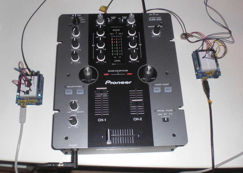
The signal from the AND gates is then fed into the mixer and sent out to the analog input of another Arduino. This Arduino converts the audio coming out of the mixer to frequencies using a Fast Hartley Transform. With a binary representation of what’s happening inside the mixer, [Andy] has something that can be converted into MIDI.
[Andy] put up a demo of this circuit working. He’s connected the MIDI out to Abelton and can modify MIDI parameters using an audio mixer. Video of that below if you’re still trying to wrap your head around this one.


Looks like he’s using the 74LS08 as a makeshift current source. LS logic typically is limited to around 1mA Ioh, whereas most modern MCUs can drive between 25-50mA per pin. Combined with the RC network it makes a low pass filter, in place of the LC chebychev filter specified in the linked article on DDS. LS logic also has asymetrical outputs, however. They can usually sink an order of magnitude more current than they can source, which means that the rising edge of signals will be filtered more than the falling edge.
A hack worthy of MacGuyver, but the tone of the write-up seems to suggest the author doesn’t understand whats going on much more than Brian does. Sort of a “I threw this stuff I found in the refrigerator together, and what do you know, it tasted good!” type of thing.
Use the series resistance to control the current, not the drivers. If you want to sink/source 1mA from the AVR, use a 5k resistor. If you want asymmetrical, have a diode + series resistor to increase the sink current, This way you get full control of the characteristics.
As you pointed out, the I/O drivers on the AVR are pretty strong (40-ish ohms impedance), so kind of silly to use a weaker driver to buffer it.
So there is a sine wave for bass, a PWM square wave for midrange – and harmonics for higher frequencies. Control signals are all kept within the ausio range the mixer is expected to handle. Analysis out output lets you determine controller settings.
I’m no professional so my spine isn’t crawling, but I’d want plenty of isolation between these analog control signals, and my precious not-yet-digitised audio.
The explanation and the video gets a humongous…HUH? I will go back to Stars End WXPN for the planet’s finest electronic sounds, it’s on right now.
Nothing like a video where you can’t hear what the subject is thinking, and the sounds aren’t wired to the capture device.
I had an utility patent registered about 15-16 years ago that _seems_ to do something similar (if I understand the article correctly, which may well be not the case): Use a cheap soundcard to create a set of frequencies that are “mixed” on your analogue mixer, then use the same soundcard to record the “mixed” signal sum and split it up to read out the fader settings.
The idea back then was to use the analogue mixer to create midi controller messages, NOT to mix the actual production audio signal on the mixer. Analogue mixers could be bought for a few bucks, cheap audio cards the same – but digital mixers were very expensive.
The system worked and I even had a few professional licensees. “Unfortunately” digital mixers became very affordable soon – well, not really “unfortunate”, since I like tech to be available to everyone :-)
That is remarkably clever
This is a very nice hack and I am sure it has quite a bit of educational value for those wishing to pursue it. However it is another example of using way to much kit to create a minimally useful output. There are a number of programs available (my favourite is http://www.hermannseib.com/english/vsthost.htm) which can turn a game controller or mouse into a MIDI controller and I have found usable controllers in the trash and thrift stores for next to nothing. It is a simple mater to replace joystick controls with rotary or linear controls and you get a couple of buttons to play with to boot.
One of the most creative hacks I’ve seen in a while.
I fixed a section of a 100 ton scale at the water treatment plant my dad works at. The signal comes from the load cell, is converted to digital for the readout, converted back to analog after some processing, sent to a board three inches away, converted to digital, maybe some more processing, then sent out as a 4-20mA signal to a SCATA system, where it is converted back to digital.
Analog to digital to analog to digital to analog to digital, in a professional setup.