There’s an old joke that says USB cables do not exist in three-dimensional Euclidian space. Try to plug a USB cable in a socket, and the first try will always be wrong. Flip it, try to plug it in, and that will also be wrong. You will only succeed on the third try, and this is proof that USB connectors exist in higher planes of reality with arcane geometries. The joke is as old as the Pythagoreans, who venerated USB connectors as gods.
The waveform has collapsed, the gods profaned, and USB connectors that exist in only three dimensions have arrived. We’re talking, of course, about a reversible USB Type A connector that will plug in the first time, every time. No need for electromancy or the “looking on the cable for the USB logo and plugging it in with that side up” method used by tech plebeians.
This discovery came after going through my daily roundup of crowdfunding press releases, eventually landing me on this idiotic project. It’s a USB charge cable that’s supposed to charge your phone twice as fast, despite the fact that charging speed is a function of current, and that’s determined by whatever you’re charging from, not the cable. Terrible idea, but they do have something interesting: a three-dimensional USB connector.
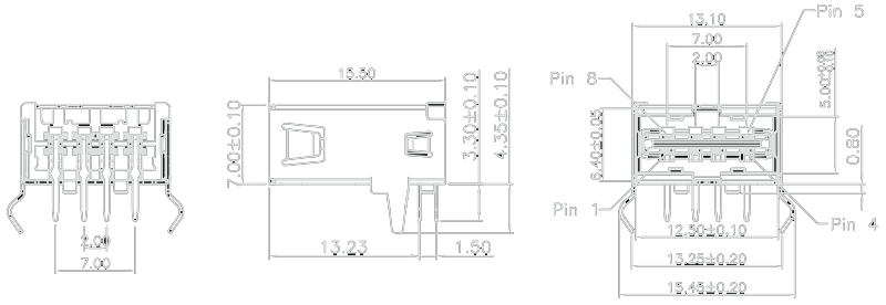
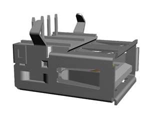 The connector isn’t the brand new USB 3.1 Type C connector that will eventually find its way into phones, laptops, wearables of all types. This is your standard Type A USB plug you’ve known and loved for the past eighteen years. The difference here is that the chunky block of plastic that has made the common USB cable non-reversible for so many years is gone. In its place is a tiny strip of plastic that has contacts on both sides. Yes, it took nearly two decades for someone to figure out this would be a marketable idea.
While searching for a source for these three-dimensional USB connectors, the only source I could come up with was Wurth Elektronik, With Farnell/Element14 carrying a selection of connectors, a few available on Digikey, and some available on Mouser. There are even a few pre-made reversible cables available, with Tripp Lite leading the game right now.
For integrating one of these connectors into your build, there’s only one thing to watch out for: the pinout for these plugs is mirrored on each side of the thin strip of plastic going down the middle of the connector. This means your VCC and GND pins will be right next to each other, your D+ and D- signal pins right next to each other, and now you have to do your layout with eight pins instead of only four.
While it may not be groundbreaking and it makes for some confusing PCB layout work, but as told by a highly successful crowdfunding campaign, this can be a real feature for a product.
If you’ve recently come across a component, connector, or part that’s unique, interesting, or downright cool everyone should know about, send it on in and we’ll take a look at it.


Semiaccurate found one of those reversible USB cables at CES:
http://semiaccurate.com/2015/01/12/tylt-makes-reversible-usb-b-cable/
Putting the USB logo side up doesn’t always work. Idiot designers like to mount things upside down and sideways to deepen the confusion. Sometimes the only way to be sure is to look at the pins.
I saw a PC case with two USB ports on the front IO.
Both opposite orientations.
As if the problem wasn’t bad enough as is. -.-
I have an old Dell like that, grrr
They did that so if the cable doesn’t fit in the first socket, move it to the next… B^)
The other day, it takes me 4 trials to plug the USB. “Maybe there is more dimensions in a USB plug than what we thought”, scientists said.
I’m really surprised it hasn’t been done before. I was thinking about this since years but never knew why no companies did that.
Also, now they should do USB plugs that you can’t put in your Ethernet port ! At least, this never happens in HDMI ports…
No but my motherboard has an eSata port that doubles as a USB – meaning you can plug either into it and it will work :)
I have an eSata that doesn’t double on the back of my desktop box. Multiple times I’ve spent way too long trying to plug in a USB because I can’t see the back of the box.
I’ve messed up some eithernet ports before by shoving a USB plug into them. I wish there weren’t the exact same width, I the dark it feels like the same port.
I don’t know how you manage to do that, even if you do it blindly and only by feeling with your fingers, the ethernet port is so big that you can put a whole finger in it, and the USB is smaller. I always guess the USB ports that way, first I find the LAN port (the only one big enough for a finger) and then i plug the USB next to it.
The IO header on my motherboard has 3 columns of similar ports right next to each other. 2 stacks of x3 usb with a ethernet+2 usb right next to it.
This machine lives in a rackmount case inside a 18u rack case. Even at the end of its slides it doesnt come far enough out to see the IO panel. The ethernet port must have a usb magnet in the bottom because thats where usb cables find their home more often than not first try.
At this point- getting a cable plugged in the first try is the first sign that something is not right.
“Sorry, baby! I didn’t mean to stick it in the wrong hole, but in the dark…”
… and THAT’s how “twisted pair” was invented!
Heh. I was pulling my hair out the other day because my computer couldn’t see my all-in-one. Turns out that, if you blindly plug the USB-B
end in, it will fit quite handily into a phone jack. :facepalm:
Because the USB organisation seems a pretty disorganised mess, I mean how many variations of “small” and “mini” plugs/sockets are there? If a 3rd part company came along and designed the full spec for the reversible one, and then started selling it for a couple years undoubtedly the USB organisation would come along and design a second and incompatible reversible one just because they can.
Best thing about “standards” there are so many to choose from
yes, indeed the USB standards committee in 1996 should have accurately predicted the advance of the computer and device industry and designed the perfect connectors before we even knew we needed them
well, making a plug not square was not exactly new, i’m pretty sure they made it square to be different from serial ports to begin with. The first “new”usb (B) and mini, had a “one way” shape. where just stuck with the square design for backward compatibility.
Eeeh, USB-C being reversable just means that it will only take two tries to get it socketed.
A little more work for the manufacture perhaps but what if the connections were crossed over inside the socket to make it a pin for pin drop in replacement for a standard socket. instead of leaving the extra wiring for the pcb.
But thinking about it it could make for an interesting option, with eight pins perhaps a read only side could make it interesting.
Think you answered (partially) your own question.
Flexibility for other uses is great.
But really, it’s a lot easier to have the pins link up on the PCB than inside of the connector ie: cheaper.
Maybe the mfg is reading people’s minds… I have some usb memory sticks that really only consist of a circuit board with the usb contacts on them… I could plug two of them into this port at the same time.
I’m not sure how read-only would work — but you could easily have a “data” side and a “fast charge” side, or two “fast charge” sides with incompatible dedicated charging signaling on each side’s D+/D-.
You could make a thumb drive or card reader with diodes on the +5V lines to detect which side was up. But for general cables you are right.
I don’t know.. “tiny strip of plastic” sounds fragile. What I really want is a small, robust connector. MicroUSB has been a nightmare for us with it’s crappy connectors, I hope Type C improves things.
This.
I’m still wanting a industrial spec USB connector (ala RS-232, with the locking screws).
+1. Even the ‘high retention’ connectors don’t always fare well in shake tests
you don’t have to want, you just have to google
http://sine.ni.com/nips/cds/view/p/lang/en/nid/210962
Neutrik FTW
http://www.neutrik.com/en/multimedia/multimedia-connectors/usb/
I use those Neutrik connectors all the time, they are good, but they are not cheap!
I want USB 3.2 to be like Apple’s Magna-sumthing power connector. In other words something that will just pop off
when the cable is tripped over.
Sorcery!
Wouldn’t the metal housing of most USB cables and flash drives short the pins on the opposing side of the connector?
My immediate thought as well. Might require some circuitry to prevent this?
It does look like the metal outer part of the A type connector would be extremely close to the pins on the opposite side to the ones in use. Even if it’s not touching I’d still be concerned that shorting would occur during the action of inserting or removing the cable.
Looking closely at the PDF drawing on the wurth site, it seems that the top pins are different to the bottom ones ones. Perhaps the pins see-saw in one direction or the other and the ones not in use withdraw below the surface of the plastic tab.
Interesting part though, might take a look.
The metal housing would be about 1.9mm from the contacts on the open side, so not really an issue.
oh great, another usb connector standard. i still dont understand the sudden jump from the mini to the micro. the micro isnt that much bigger and the mini seems more structurally robust. its like they want us to break things so that we can buy more crap.
This is exactly what they want !
The micro connector is different in an important way: The retention springs are in the cable, instead of in the device.
This means that the micro *socket* is more durable, while being smaller and cheaper than its mini counterpart. The breakable bits are all in the cable, which is much cheaper to replace than the device hosting the socket (unless you’re buying solid gold USB cables. In that case, I have some real estate in which you might be interested.)
MicroUSB is like Java-just because it’s everywhere doesn’t make it superior.
I have several Android handsets and one Lumia920 handset that says otherwise.
Cause of death? broken MicroUSB port. Whether the plastic alignment pin snaps or the socket itself breaks off inside of the phone it’s time for this connector to go away.
A lot of time it’s the circuit board not holding up to the stress of supporting a plug and cable; I’ve seen two B&N Nooks die that way. Can’t be repaired because it rips vias out of the multi-layer board. That’s not on the plug standard but on the designer of the board and device.
Well, I AM GLAD the phone manufacturers (exc. for that one stuck up company) decided to standarize on one charging/USB cable. But I do find it much harder to plug a micro into my Swampscum Galsexy 5 with its 3.0 connector.
By the way, why do they use USB 3 if they are giving a USB 2 cable with the phone ? Or why don’t they give us USB 3 cables ? Plus, it’s not like I need to transfer a lots of gigs at high speed on my phone. It’s a darn phone !
speak for your self, i own 50 micro cables, i own exactly 1 mini cable, and i share it between 3 different dev boards.
The micro socket is more durable… 10,000 plug/unplug cycles rather than 5,000 for the mini or 1,500 for the standard. And the springs are no longer in the socket, but the plug. Of course, it’s also thinner. The phone industry didn’t want to get stuck with the Mini-B or Mini-AB just based on the need to continue to support that thickness in their devices.
“It’s a USB charge cable that’s supposed to charge your phone twice as fast, despite the fact that charging speed is a function of current, and that’s determined by whatever you’re charging from, not the cable.”
Well, actually the cable is an important factor of the charging speed. I bought on of those cheap USB voltage/current monitors and tested all my cables with it connected. A quality brand cable charged my phone with the full 1 amp whereas a cheap dollar store cable only gave my phone about 400 mA. This is probably caused by the higher lead resistance in the cheap thin cables.
No, it’s caused by the resistor in the USB connector (typically the mini or micro end as they are also five pins) which tells the device to charge at a higher rate as it’s not just a bogo datacable.
No, I’ve checked the best and worst cable with a dmm. There are no resistors between any pins on the micro-usb.
I have a super cheap (and thin) chinese cable which charges phone but it’s takes two days. Normal typical cable charges the same phone in 3 hours. If leads are too thin, they have high resistance and more voltage drop.
^this
Since Amazon changed how they do listings, I got both nice cables and cheap crappy cables from different vendors. The wires in the cheap cables are stupidly thin, just three of strands in in each line in one I tore apart. I ended up using the strands to solder data line jumpers in some SMD rework. I couldn’t charge and use the phone at same time with it.
The nicer ones are much thicker. I can easily recharge a device while pushing the device to its limits.
The resistor is usually in the charger, not the cable. The charger and the cable are both dumb and the device is smart. The device uses the resistance across the D lines in the charger to ID the charger (a hack on the USB spec which actually requires the charger to be smart as well). An number of reasons could cause the device to charge at a slower rate, including a large V drop on the source when it attempts to draw current.
In any case, while you may have a crap cable that hampers charging, a cable that the speeds up charging 2X is pure fantasy. The devices built in charge controller decides what the max current draw should be and appropriate charge rate for the devices hardware and battery.
That’s exactly how it’s supposed to be for a normal cable. I’m assuming that the only magic in this cable is the switch which disconnects D+/- from the A end and puts the appropriate resistors across them to make the iPhone believe it’s connected to a high current charger. Otherwise the phone’s charge controller will limit itself to the standard 500mA VBUS.
The same thing in a phone-agnostic inline cable can be had on eBay for a couple of bucks, or roll your own with a reclaimed USB A extender and a couple of resistors.
I think you are right.
So for this product to work you have to make sure of a few things: first the resistance in power lines has to be small enough to allow for a higher current. Second, by disconnecting the data lines and connecting the proper resistance you are telling the phone that no, you are not connected to a computer port with 500mA limit, you are connected to a charger that is capable of delivering more. Third, you rely on the fact that many motherboards don’t have a current limit per port, or it is pretty bad, so you can actually draw close to 1A per port, provided you don’t do that from more at the same time.
I think it is possible to make it, but there are limited number of cases where it will actually work.
Some motherboards apparently have been designed with 500ma per *pair* of ports. I have some USB hard drives that on some computers will run just fine off a single port while on others I must also connect the ‘vampire tap’ power only connector to get enough current.
From the Indiegogo page:
“How Does the SONICable work:
“When the switch is OFF: Its like a normal USB cable, charge and sync.
“When the switch is ON: All of the power is wasted on charging, sync is disabled”
So you see, it works by wasting all the power on charging instead of syncing.
Don’t you already have USB cables that fit both ways ?
http://www.newsfiber.com/p/s/m?msg=60T9ta6yJvs%3D
But I guess these won’t fit in these reversible sockets ;)
actually, it would… in 4 different ways :-)
HAH! This non-euclidian stuff is awesome! I thought I was the only one that’s had the three-turns issue! Now four?!
I dig how this thing just uses a PCB, and I dig that PCBs are much stronger than plastic. I also dig the inspiration that using a PCB as a USB connector could have on project-ideas. But I’ve run into several USB females with shitty metal-sheilding that allows the connector to wiggle inside the housing. This system would not play well with those. (Same for the reversable female, and shitty cables).
It all sounds very “timey wimey” to me.
A note about the “idiotic charging cable” mentioned above. Some devices like Ipad for example read the voltage from the data lines of the USB port to understand if it is connected to a computer port, a low power USB charger or a high power USB charger. I think that cable modify the voltage on the data lines, exclude the data transfer, and make the device think to be connected to a USB charger and so sink more current.
I looked at the idiotic project, and while it seems far-fetched that it could charge twice as quickly, I’m wondering if it might be somewhat quicker for two reasons: thicker wire, offering less resistance; some type of shunt that pulls current intended for sync and uses it for charging. I don’t know enough about the amount used in sync, or lost in thinner-gauge wire, to say whether the claim of “twice as fast” is far-fetched, but is it plausible that it could be measurably faster? Thoughts?
Current is a result of voltage and resistance. You cannot just “push more current”, the device has to “pull it” so to say.
Now, disconnecting the data lines might trick some phones into thinking it’s a wall charger, and thus drawing more current. But I think that’s about it. No real magic happening.
Right. I wasn’t trying to suggest that we were “pumping” more current here – just making more available due to lower resistance, and shunting data-line current to the charging lines. I don’t know how much current a computer can safely put out through a USB port. Anyone know?
I think most USB controllers would detect that as a short and shut down. At least that’s what my laptop controller would do if I shorted a D line directly to a power rail when I was fiddling with my USB projects.
Ah, that makes sense. Thank you for the non-snarky reply! I’m pretty content with my phone and kindle charging at regular speed, so I doubt I’ll be experimenting…
There should be very little current going over the data lines. If you take their explanation at face value, you might see a fraction of a percent decrease in charging time. I think others here have provided a better explanation in that the cable probably bypasses the current limiting in the phone charging circuit meant to prevent you from frying your computer’s USB ports or overloading a cheap wall wort. I wonder how damaged computers and possibly event fires that this cable will result in.
The USB protocol has a negotiation to detect if it’s a high-power charging device where it disconnects the data lines and dedicates to charging. Then it can do 1A, which is twice as much as 0.5A of old USB obviously..
I am still pondering if plugging the USB cable the right way, from first try should be treated as a super secret thing available to a select society or an idiot test.
I mean, i get there are screw up designs out there, but for 99% of the things it’s a simple rule: you have to see the logo.
Good thing we have you around, then!
Unlike Ethernet cables, the USB connectors do not have the upside down option. So it is either at 0 degrees or 90 degrees. Knowing the orientation of your PCB or motherboard, you should be able to figure it out.
Now if only you can’t accidentally plug it in the wrong connectors.
Errr… 180 degrees.
Sure it will go in at 90 degrees, if you push hard enough.
That’s what she said.
he means 90 degrees, like the vertical-mount USB sockets on routers. There are horizontal and vertical mount USB sockets for PCBs, but panel mount USB sockets can be mounted in any arbitrary orientation.
That requires you to look at the plug before you plug it in. And remember which way is the top on side mounted sockets, especially the ones you can’t just look at.
in other words USB is not for blind people
The logo is raised plastic on the cable while the “bottom” side is smooth. If you can’t do it by sight or by feel, you have much bigger problems.
So you’ve never seen an ipod usb cable? The logo is NOT raised plastic.
It is after you poke it with a soldering iron.
The bigger problem wouldn’t be with the consumer. Common sense would dictate that the USB trident should be up om the same orientation as up with the device it is being plugged into. I have an Acer tablet where the socket is bass awards. The trident goes in align with the rear camera not the front camera. And with a brain injury I have problems with that sort of shit. Anyway touch screen devices m seem to be totally incomparable with blindness.
Yeah I am calling you out on your concept of 99% of the USB ports being mounted in the same orientation.
Plus with mobile devices it becomes even more random because there is no ‘up’ to the design crew since they go by how the PCB is mounted and how the USB port is just ending up because of the PCB’s orientation, as an afterthought.
I wonder what kind of plastic they are using for the inner connector? A plastic connector that thin would break quite easily, especially given the additional space in the connector to make it reversible. Although they could always fix this by building double-sided cables as well to fill up the empty space while remaining reversible (So that the connector and cable actually houses two ports rather than just one).
That way you’d have:
(-) D1+ D1- (+)
==insulator===
(+) D2- D2+ (-)
Then you could potentially have your “Double speed charging cables” by just connecting to both sides of the port at once.
But the one thing that I’ve always wondered: what ever happened to hermaphroditic connectors? IBM used to use one for networking. And given the serial nature of everything nowadays, they’d be perfect for modern connectors.
“IBM used to use one for networking. And given the serial nature of everything nowadays, they’d be perfect for modern connectors.”
Yeah those were “token ring” connectors, and no, they sucked big time with terrible intermittent issues, there is a good reason they were abandoned. Just ask ANYONE who had to maintain a token ring network, what they thought about those stupid connectors.
Aren’t they same connectors use in HAM and CB radio equipment?
No. The hermaphroditic Token Ring connectors bear some superficial similarity to Anderson Power Poles, which are a style of connector sometimes used for 12VDC power connections on Ham equipment. Both IBM Token Ring connectors and Anderson Power Poles are hermaphroditic. But the similarity pretty much ends there.
Old ethernet cabling systems, using coax, often used BNC connectors. BNC connectors are one of the fairly common connectors used for antenna and other RF connections in Ham radio equipment, especially at low powers, roughly below 50 watts or so. But I don’t think BNC was ever used for Token Ring.
73 de AG6QR
Yup, BNC was used for Token Ring. The cables were close enough in spec they would also work for 10 Base-T. Token Ring got beat by Ethernet for a couple of reasons. One was the system never went faster than 11 megabit. The other was it couldn’t handle as large of a LAN as Ethernet, especially when using using switches instead of hubs on Ethernet.
Oh a third reason. All Token Ring cards had this plastic dipped circuit board soldered on which the manufacturers were required to buy from the company that invented the system. Sort of like having to buy a physical license for every board made. Had the company developed a faster speed system, faster than 100 megabit Ethernet, and made it able to handle larger networks, it might have stood a chance.
But when 100 megabit Ethernet was introduced, Token Ring systems got yanked out and boxes of cards and cable got stuffed into storage closets in companies across the land.
Dell actually has some sort of double-tall USB-ish connectors in some of their old laptops… they’re used to power external CD drives. Regular USB cables use the lower slot, but Dell’s goofy ones are twice as tall and plug into both.
http://digilander.libero.it/electrons/PD01S.html
Basically a proprietary version of PoweredUSB.
http://en.wikipedia.org/wiki/PoweredUSB
What about a RRTC, a radial rotationally tolerant connector. Sounds good, like… oh it exists, an audio jack.
You mean the one where you short all the pins to the previous one before they reach there position? Nah
Yeah, fine for audio, not so much for +5v.
Actually It does work. The old IBooks plug was a 2.5mm audio jack.
Actually it doesn’t work, that crappy power connector was the first thing to die on my old ibook.
I had that problem some years back when I was using a mini-jack as a power cable and power switch (remove to turn on) for a remote controlled glider. One day, I had not pushed the plug in all of the way and the glider caught fire while sitting in my car. Fortunately I was there to put it out quickly. I found that the solution was to use a stereo connector instead of a mono connector and leave the middle ring unconnected. A similar thing could be done here by properly interleaving data and power rings.
it was only about 100 years ago that audio engineers figured out that it was a bad idea to pass microphone power through that type of connector
Electret mics are still made that run from “phantom” DC power on the audio lines. The DC has to be exceptionally well regulated and ripple free.
what happens when you try to plug in Apple’s reversible wire?
[img]http://www.inrumor.com/wp-content/uploads/2014/09/reversible-usb-460×290.png[/img]
404
I have to call shenanigans on this whole connector idea.
A reversable type-A connector, barring some special sauce in the latch that I’m not seeing in the datasheet, is going to have a harder time holding its cable in place. A lot of force could wind up on the tongue of the jack, since the cable has more room to wiggle up and down, barring the latches. If not a chance to break, that’s a bouncy electrical connection. Bounce is bad.
USB type-A connectors are only good for about 1,500 connections per datasheets. Thus, it’s not ideal for frequent connects. One of the main goals of a reversable connector is to make connections convenient. Thus a type-A connector seems a poor choice for reversability.
I think these two reasons (plus costs, of course) are why we don’t already see these everywhere. I strongly suspect someone has given it a shot in the last 18 years of USB, and it just wound up being neither reliable enough nor worthwhile.
(Editors: also, the “a reversable USB type A connector” link in the post doesn’t point to such a connector. Maybe it was poorly phrased, and the link was just supposed to demonstrate a standard type A connector? Or wrong link?)
I like type-C, though. Nevermind that everyone griping about USB being a hyperprism seems to have forgotten the joys of bent mini-DIN pins and a dozen more DC power connectors. Now get off my lawn :)
That SONIC cable isn’t as stupid as it sounds. All they’re really doing is giving you a cable that switches between a data/sync cable (which can charge at 480ma max) and a charge only cable, likely with the d+/d- pins shorted on the mobile side and disconnected on the computer side, which then of course tells the device to switch to full current charge mode (1A or more).
While this wont work from most computer USB ports. It would let you use one cable for both syncing and charging from a USB charger plug and getting the optimal current from either scenario. This is how they use it in the demo, with a charge cube in charge mode and a computer in sync mode.
Some computers also support 1A charging USB ports so this would work on those as well. Those USB ports are usually yellow.
The $27 price however IS stupid. ;’)
And USB 3 is designed for 900mA per port. A fast charge adapter will let you get the full charge rate on a device that only supports USB 2.
I can’t believe how many people have been duped into buying these ‘double your charging speed’ cables. My friend bought a different one from Kickstarter a few months ago.
I told him it was nonsense and he went out and bought a PortaPow to prove me wrong (Portapow measures usb power – https://www.youtube.com/watch?v=GN7_40ZQ_wI ).
So he connected his iphone to the original charger and it was charging at around 1.5 amp. Then to an anker ‘smart charger’ and again its around 1.5 amp. Then he used his special new cable and it dropped to around 800mA ha! After turning OFF the ‘boost’ setting on his fancy cable it went back up to 1.5 amp.
Basically, the only real world situation where it will speed up charging is when connecting it to a computer which would otherwise only output 500mA. But guess what happens when the cable tricks the phone into thinking it’s attached to a high current charger? The phone tries to pull more current and the computer either turns off or throws up a message saying an attached device tried to draw too much current and that the USB port has been disabled until reboot.
Sure, some computers will happily push out more current but many wont.
‘Fast charge’ cables have existed for a long time and can be bought very cheaply or made at home quite easily.
Rated 1500 cycles v.s. up to 5000 for a USB 3.0 connector.
this is the one(and only) area where AAPL did something useful and innovative: the lightning connector. I dont use it but if I had a lightning connector socket I would probably install it to replace a broken microusb. micro usb can take me 2 tries even when I can see where it goes. micro usb 3.0 is what gets me in the dark. sometimes it does take 3 or more tries. if you look at the back side, you can be easily misled into believing the small side is the big side. my main issue is that there should be more properly designed right and left angle connectors. I know my original samsung issued microusb3.0 caable won’t last a year because I have to put the wire in abusive positions when simultaneously charging and using the note3
I do love those usb 3 transfer speeds though.
It’s been more than a year since reversible USB plugs and receptacles first came to the market. It’s nothing new, unless if they’ve figured how to insert a reversible plug into a reversible receptacle which is not possible so far.
http://cdn.akihabaranews.com/sites/default/files/styles/akiba-custom/public/field/image/buffalo.universal.usb_.plate_.png
http://car.watch.impress.co.jp/img/car/docs/627/049/08_s.png
hey, i found this pretty useful and cool, can HACKADAY do some kind of repository? for the community? so we can all upload our own models of parts and we can al share, yes? i have been collecting 3d parts because i use solidworks a lot at work to build models and stuff, i’d love to share the parts i have, what you guys think?
the first paragraph though XD its true tho alway 3 even when I know which way it goes
But why doesn’t this kind of connector cause short circuits? The metal can on the end of the cable must get very close to the unused set of USB pins.
I am surprised nobody mentioned the obvious conclusion: USB cables are spin-1/2 objects (it takes a 4 \pi rotation to fully flip them)/
Well played, sir. I thought it was just an elongated hypercube :(
Cables makers and retailers are the drug dealers of the electronics industry. Oh yeah sure you can buy that normal heroin or you can buy my gold-plated, oxygen-free, audiophile, double-shielded heroin that vacuums your house while you are out. They both do the same thing but I can charge you 5-10 times what the product is worth because most people have no f*cking idea what goes into them. At least VGA cables aren’t that common so I can understand mark up on those.
How about also changing the size of either the USB plug or the RJ45.
…Because a USB A will fit nicely into an Ethernet RJ45 when blindly trying to stick a USB plug into the back end of a desktop.
Done it about four times now over the past 15 years. And wondered why my USB device doesnt work until I go and have a proper look….
Maybe 5 years ago I met a guy and his son at the TRW swap meet who was selling a USB type “A” Adapter that allowed you to plug it in either way. His son had named it the “Flipper”. I got the impression that he had patented it.
But, selling USB connectors to HAMS didn’t seem like the most profitable strategy.
But wait… doesn’t the devices circuitry control the charging of the battery used in today’s devices? Somewhere I read in their information “…SONICable will be available in 2 versions, micro USB or lightning…”. The micro USD as a D shape of sorts, there goes the reversibility. I’m not sure it it was something that existed before Apple start using it, I like the bladed connector thy started using on the appliance end of the charging/data cable. I hope it existed previously, and if apple hasn’t been allowed to patent it erroneously, as I’d like to see it gain popularity. May not be the best for data transmission speed, I don’t know, but I imagine it’s used for charging more than data. I really doubt there will be return to the coaxial type of charging connector.
A while back on Gizmag I saw a USB cable with a Type A end that had a double sided middle blade with a spring loaded part on either side. Whichever way the connecter was pushed in, one sprung piece would push in while the other stayed out to provide support to the contact blade. Clever design but does not appear to have made it to market.
The biggest failing of USB is the same reason for the big fail of Apple putting the antenna gap on the iPhone 4 precisely where most right handed people would place the tip of their little finger.
Engineers. They know *exactly* how what they are building is supposed to work. They put an antenna gap *there* and of course they know that bridging it with a fingertip will short it so in testing they do not do that. Thus, the problem never appears in testing and they’re befuddled when user-knows-nothing-about-antennas grabs the phone and instantly shorts out the antenna. Moving the gap closer to the corner or at the top or bottom end of the phone would have prevented the problem.
With USB connecters, inserting cables in the lab is never a problem because the engineers make sure they have a clear view and precisely aim and align their expensive engineering prototypes before plugging them in.
If they’d put the connecter on the back of a computer simulation device (ie a box), up against a wall, then try to fumble around to plug the things in, USB ports would have been designed with a sloped/rounded entry bezel, without any sharp edges to snag the end of the cable plug shell, and with an easy to orient entry key that wouldn’t even begin to insert into the port the wrong way.
They also would have specified a minimum distance vertically and/or horizontally between connecters to accommodate things larger than the end of a USB cable. Not because of being able to foresee things like flash drives but because it’s bloody damn difficult to plug in one cable around the back of a computer and even harder to get one in right next to the first.
The only USB connecter design so far that begins to meet any of those user friendly ideals is the original Type B. It has an obviously non-reversible shape, with large enough non-symmetry that it’s possible to tell by feel because until it’s the right way around it doesn’t come close to feeling like it should be going in. Mini B comes in a close second, in cases where the casing around the port is tightly fitted and shaped instead of a rectangular hole spaced away from the connecter.
USB 3.0 connecters are a bit of a surprise, being backward compatible with any previous Type A cable and Type B micro. The 3.0 Type A cable connecter can even plug into a 1.x/2.0 Type A port and transfer data at the slower speed. Type B micro simply plugs into one end of the 3.0 micro port. The one that isn’t backward compatible is the 3.0 micro cable connecter, it can only plug into a 3.0 micro port due to the added pins for 3.0 being stuck onto one side of the 2.0 micro connecter. That non-symmetrical shape does help a bit with blind fumbling plugging in because when it’s the wrong way around it doesn’t feel like it should be going in, unlike 2.0 micro B.
There are a lot of computers with horizontally mounted USB ports that are upside down. The greatest offender was one of the earliest large scale adopters of USB. Apple Computer. How many million CRT iMacs did they produce with upside down USB ports on the side? I would’ve thought detail obsessed Steve Jobs wouldn’t have let that out the door. If the ports have to be mounted on the underside of the board, then you call up the part manufacturer and tell them you want x million of them designed so that when installed, the cables will plug in logo side up like the USB Implementers Forum says they are supposed to.
I’m wondering why nobody talks about this concept that would auto solve the wrong way and still maintain backward compatibility to type-A connector.
http://www.wired.com/images_blogs/gadgetlab/2011/01/double_usb.jpeg
It’s a nice idea but I suspect it would be fragile in practice. I’d be interested in trying one out for myself though. Are they still available?
Sadly this connector never made out of concept into market.
In my opinion this connector would be far more robust than those type-A design with a “tongue” in the middle, which is susceptible to breaking if there is any much bending force or misalignment. This design doesn’t need to reduce the thickness of the “tongue” and still fill in the gaps with conventional type-A connector.
If the “tongue” has to go so thin as to be compatible with conventional type-A connector, we might as well see the same case with current micro connectors popular in mobile devices. Read up the comments above and you’ll find some rants on micro connectors that broke on some bending force.
Since you own the devices most of the time you could also get a bunch of small stickers and stick a dot on the plugs and on the ports so they match and you know which side is which.
But as the write-up says, type-C connectors are already appearing in devices, even apple ones.
I want to see USB ports with a solenoid or motor that pushes the plug out when the user tells it to eject, like the old Macintosh floppy drives used to.
Friggin’ Brilliant!