Postage Scale

Fixing A Broken Postage Scale

[Starhawk] had an old Pitney Bowes G799 postage scale that wasn’t working as it should. After years of faithfully measuring packages and cooking ingredients, the scale stopped working. At first it fell out of calibration. Then the power up sequence stopped working. The scale normally would turn on, light up the entire display, then change to dashes, and finally set itself to 0.0 lbs. In this case, it would get stuck at the dashes and never change to 0.0.

[Starhawk] ended up purchasing another duplicate scale from eBay, only to find that when it arrived it had the exact same power up problem. Using deductive reasoning, he decided that since the scale was broken during shipping the problem would likely be with a mechanical component. He turned out to be correct. The cheap momentary power button was at fault. When pressing the button, the contact would get stuck closed preventing the scale from zeroing out properly. [Starhawk] easily fixed his problem by replacing the switch.

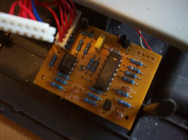
Next [Starhawk] replaced the old scale’s LCD module with one from the new scale, since the old one looked to be on its way out. The scale still had a problem correctly measuring weight. [Starhawk] tried swapping the load cell from the new scale to the old one, but he found that the new load cell had some kind of problem that prevented the scale from zeroing out properly. The solution ended up being to use the newer “analog board” as [Starhawk] calls it.  The end result was the old scale with two newer circuit boards, an older load cell, and a new power switch. Next time it might be easier to just build his own scale.

Simple Pen Plotter

Simple DIY Pen Plotter, Great First CNC Project

[Morten] has been busy recently making a pen plotter. It is a simple and elegant build that he completely designed from the ground up. There are no extra frivolous parts here. The frame is made from laser-cut plexiglass which makes fabrication easy if you have access to a laser cutter. Two NEMA17 motors are responsible for the machine’s movement. One moves the pen carriage back and forth by way of a belt. The other is connected by laser-cut gears to a roller bar, scavenged from an ink jet printer, that moves the paper media forward and aft underneath the pen.

The software chain used here is sort of uncommon compared to other inexpensive DIY CNC machines we see here on Hackaday. [Morten] creates his geometry with Rhino, then uses a plugin called Grasshopper to generate the g-code that controls the machine. That g-code is sent using gRemote to an Arduino flashed with the contraptor.org g-code interpreter. A RAMPS board takes the step and direction signals generated by the Arduino and moves the two stepper motors appropriately.

In typical open-supporting fashion, [Morten] has made his design files freely available for anyone to download. His plotter moves the pen side to side and the paper front to back in order to draw shapes but that’s not the only way a plotter can work. Check out this polar plotter and this one that hangs.

Check out the video after the break…

Continue reading “Simple DIY Pen Plotter, Great First CNC Project”

Alarm1

Adding WiFi And SMS To An Alarm System

[Don] wanted to bring his alarm system into the modern age. He figured that making it more connected would do the trick. Specifically, he wanted his alarm system to send him an SMS message whenever the alarm was tripped.

[Don] first had to figure out a way to trigger an event when the alarm sounds. He found a screw terminal that lead to the siren. When the alarm is tripped, this screw terminal outputs 12V to enable the siren. This would be a good place to monitor for an alarm trip.

[Don] is using an Arduino nano to monitor the alarm signal. This meant that the 12V signal needed to be stepped down. He ran it through a resistor and a Zener diode to lower the voltage to something the Arduino can handle. Once the Arduino detects a signal, it uses an ESP8266 WiFi module to send an email. The address [Don] used is the email-to-SMS address which results in a text message hitting his phone over the cell network.

The Arduino also needed power. [Don] found a screw terminal on the alarm system circuit board that provided a regulated 12V output. He ran this to another power regulator board to lower the voltage to a steady 5V. This provides just the amount of juice the Arduino needs to run, and it doesn’t rely on batteries. [Don] provides a good explanation of the system in the video below. Continue reading “Adding WiFi And SMS To An Alarm System”

Spliced Animations Come To Life On Their Pages

Remember those flipbooks you doodled into your history textbooks while you waited for the lunch bell? [Maric] takes the general principles of flipbooks and turns them on their head, giving our brain a whirl in the process. By splicing multiple frames into one image, he can bring animations to life onto a single page.

The technique is simple, but yields impressive results. By overlaying a pattern of vertical black bars onto his image, only a small fraction of the image is visible at any given point. The gaps in the pattern belong to a single frame from the animation. As [Maric] slides the pattern over the image, subsequent frames are revealed to our eyes, and our brain fills in the rest.

A closer look reveals more detail about the constraints imposed on these animations. In this case, the number of frames per animation loop is given by the widths in the transparency pattern. Specifically, it is the number of transparent slits that could fit, side-by-side, within an adjacent black rectangle.

The trick that makes this demonstration work so nicely is that the animated clips finish where they start, resulting in a clean, continuous illusion.

Don’t believe what you see? [Maric] has linked the pattern and images on his video so you can try them for yourself. Give them a go, and let us know what you think in the comments.

Continue reading “Spliced Animations Come To Life On Their Pages”

Hacklet 30 – Robot Arm Projects

Robot arms – they do everything from moving silicon wafers to welding cars. Many a hacker has dreamt of having their own robot arm to serve them beer help them build projects. This week’s Hacklet features some of the best robot arm projects on Hackaday.io!

robotarm1We start with [4ndreas] who is building this incredible 3D Printable Robot Arm. Inspired by large industrial robots, [4ndreas] has given us an entirely 3D printable design. [4ndreas’] 3D design experience really shows here. This arm looks like it just finished work at a local assembly line! The arm is BIG too – printing the parts took him about a week, and used around 1.2kg of ABS filament! [4ndreas] has recently split the project off into two halves: his blue arm is driven by stepper motors, while the orange arm is a DC motor affair. Both of the arms can use his awesome gripper design. Check out the project page for videos of the arm in action!

6dofarmNext up is [Dan Royer] and his 6DOF Robot Arm. [Dan’s] didn’t want to spend upwards of $10,000 on an industrial arm, so he built his own from wood, plastic, and easily obtainable parts. As the name implies, the arm has 6 degrees of freedom. The electronics consist of beefy NEMA 17 stepper motors and a RUMBA controller, which was originally designed for 3D printers. Dan even created some novel encoder mounts. Each joint has an encoder, which will allow the robot to run as a closed loop system. [Dan] originally entered this arm in The Hackaday Prize 2014. While it didn’t get him to space, we’re betting it will be able to get him a soda!

MeArm

No robot arm Hacklet would be complete without featuring [ben.phenoptix] and the awesome MeArm. MeArm is a pocket-sized robot arm which uses tiny 9 gram servos for locomotion. It’s built from laser cut acrylic and standard hardware. We loved the MeArm so much that we featured it as one of the challenges in our Embedded Hardware Workshop in Munich. More recently, [Ben] and MeArm have had a great run on Kickstarter. Let’s hope those arms are good at stuffing, addressing, and mailing out packages!


owiFinally we have [Kenji Larsen] with Reactron material transporter. The material transporter is just a small part of [Kenji’s] larger Reactron project. It started with an OWI-535 robot arm. The OWI is really a toy – a plastic kit which builds an open loop DC motor driven arm. [Kenji] has put some serious time into modifying his particular arm. He experimented with molding his own potentiometers for each joint before settling on a printed circuit board based design. Once the new system was in place, he found that his resistors were good for about 10,000 cycles. Not bad for a modified toy!

There are quite a few robot arm projects we weren’t able to cover in this edition of The Hacklet – you can check them all out on our brand new Robot Arm Projects List!

That’s it for this Hacklet, As always, see you next week. Same hack time, same hack channel, bringing you the best of Hackaday.io!

Make Awesome, Win Smoothieboard

If you haven’t looked around the RepRap project in a while, you probably haven’t heard about the Smoothieboard. It’s an extremely unique electronics board for 3D printers, laser cutters, and CNC machines that is trying to get away from Atmel and AVR microcontrollers and towards more powerful ARM micros. On the Smoothieboard, you’ll find enough five motor drivers, six big ‘ol MOSFETs for hot ends, fans, and beds, enough thermistor inputs for just about anything, and an Ethernet jack, because all 3D printers should be able to run headless.

The team behind the Smoothieboard has decided there’s not enough awesome included in the Smoothieboard already. To fix this, they’re opening up a contest where coders, documentarians, graphic artists, and creatives of all types can contribute to the Smoothieboard project. What’s the prize? A Smoothieboard, duh.

The Smoothieboard team is looking for a few good coders, builders, or anyone else to contribute to the Smoothieboard project. If you have an idea that would work with the Smoothieboard – a web interface like Octoprint running on the Smoothieboard, better documentation, graphics, or just want to build a five-axis CNC mill, this is where you sign up. The prize is a Smoothieboard 5XC, the top of the line board with five motor drivers.

Of course you’re always welcome to not contribute to open source projects, and for those consummate consumers, we have the Smoothieboard 5XC available in the Hackaday Store.

You have until February 15th to come up with a great project idea for a Smoothieboard. The best 30 project ideas will be chosen, and those projects will get a Smoothieboard. Actually building a project in a month isn’t a condition of the contest; the best idea wins.

Ice Clock

Binary Clock Fit For Queen Elsa’s Ice Palace

When life gives you lemons, you make lemonade. When life gives you freezing cold temperatures and a yard full of snow, you make binary clocks out of ice. At least that’s what [Dennis] does, anyway.

[Dennis’] clock is made from several cylindrical blocks of ice stacked on top of one another. There are six columns of ice blocks. The blocks were made by pouring water into empty margarine containers and freezing them. Once they were frozen, [Dennis] bore a 5/16″ hole into the bottom of each block to house an LED. Wires ran from the LEDs back into the drainage port of a cooler.

The cooler housed the main electronics. The LED controller board is of [Dennis’] own design. It contains six TLC59282 chips allowing for control of up to 96 LEDs. Each chip has its output lines running to two RJ45 connectors. [Dennis] couldn’t just use one because one of the eight wires in the connector was used as a common power line. The main CPU is an Arduino. It’s hooked up to a DS3234 Real Time Clock in order to keep accurate time. The oscillator monitors temperature in order to keep accurate time even in the dead of winter. Continue reading “Binary Clock Fit For Queen Elsa’s Ice Palace”