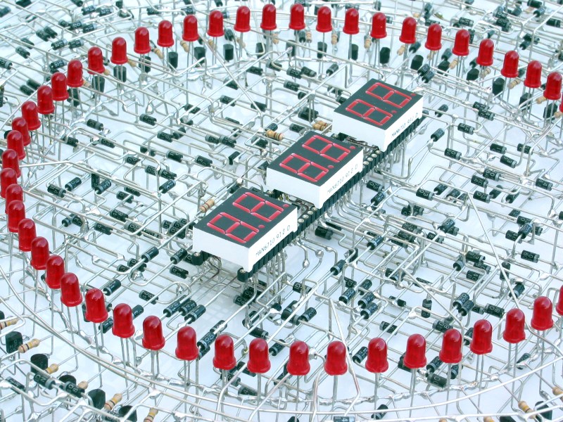
This mind boggling piece of art took hundreds of hours to make over a period of three years. The entire structure is composed of thousands of components, all of which are part of the clocks circuit. They call it, The Clock.
Each component was hand soldered in this ridiculously complex 3D structure. They have a typical artist statement, but you know what — for once it’s actually pretty intuitive.
“The Clock” has digital pulses flowing inside every single wire and every single part. These synchronized pulses, all intelligently controlled and channeled through every circuit, is a binary “dance” of hundreds of bits of information coming and going from one section to another. All working in unison to display the flow of time.
The clock works by taking in mains voltage and counting the frequency of pulses — in North America it’s 60Hz — conveniently a unit divisible for time. However if you were to take this clock elsewhere, perhaps where AC cycles at only 50Hz — the clock’s not going to keep accurate time.
It has no buttons — but you can change the time using a “Time Adjusting Magnet” over certain areas of the clock which feature micro electro-magnetic switches. The whole thing weighs about 14 pounds and consists of 1,916 individual components! Wow.
This has gotta be up there with some of our favorite clock builds we’ve ever seen on Hack a Day, perhaps with it only being second to this home-made Atomic Clock!
[Thanks Arthur!]


amazing.. wonder why a 7 segment display was used and not discrete LEDs. That would have made the design even more ethereal.
No video?
All those diodes! What would be their function?
I bet the design uses diode-transistor logic.
You can see them. Plenty of 1N4003 and MPS6531. Very cool job.
I believe you win that bet.
Two diodes make a two input AND or OR gate. Add a transistor and they are NAND or NOR. A transistor alone is a NOT gate. A number of these gates can make a XOR gate. Diodes can also be addressable ROM to use as a Binary to Decimal decoder or BCD to 7 Segment decoder. Gates make up divide by 10 and divide by 6 counters.
Awesome project. Just getting the spacial component density would have been a huge challenge.
It’s basically just a huge shift register.
Amazing how I can reduce 3 years of work to a single sentence :-)
I wish I had the skill/patience to make one. If I tried it would no doubt look like crap.
I’m sure part of the 3 years was breadboarding the circuit to prove it worked, too.
7 segment charater roms :)
epic
Speachless….
‘They have a typical artist statement, but you know what — for once it’s actually pretty intuitive.’
Amen! I’m so sick of pretentious art-speak. This artist isn’t ‘Challenging the common assumptions of post-consumer design’ or ‘Exploring the intersection of chronological perception and esthetic expectations’- they’re just making a cool looking clock. If the work doesn’t stand on its own all the fancy words in the world won’t make it any better.
This is amazing, clearly presented work. Thanks.
Heh. Re: artists statement –> “The Painted Word” by Tom Wolfe
On the website I didn’t see a picture of it powered or a video, though. So… does it really work?
From the site:
“It took hundreds of hours in the period of 3 years to create this hand-made, totally unique, masterpiece of art. ”
and
“Are there any warranties?
There is a LIFETIME LIMITED WARRANTY on all of my works of art.
Click here to find out more about the warranty. ”
Sooo…. It looks like he sells them. Better put in your pre-order now since it’s going to he 3 years before the next one is done :)
I find myself wondering if the circuit diagram is as beautiful as the circuit itself. Whether it is or isn’t, this is a stunning clock build.
I’d love to see the circuit, but he doesn’t have that on the site. Probably considers it proprietary.
Interesting piece of work. I followed through to the webpage and found it interesting he “signed” his work with a piece of wire bent into a signature.
I wonder if they made a freeform version of this?
http://www.transistorclock.com/tranmanual.pdf
nice. good link.
That’s how I would do it — start the clock design using the schematic at the back of that manual (add the ring of LEDs, etc…). Then, using a PCB layout program, manually place the components, then auto-route a 3 or 4 layer PC board. For the final clock assembly you could then build up each layer of the clock using the PC board layers as a guide, starting the build with the back layer. “Easy!”
The website says it runs on a 12VDC adapter but the text discusses counting 60Hz pulses. I suspect it’s 12VAC.
Also, I wonder why he used 1N4003 diodes? Why not 1N914/4148’s or even 1N4001’s?
Probably doesn’t matter, all could have worked.
The 1N4003 diodes have thicker leads than the 1N914 / 1N4148’s. The smaller diodes would hold the physical structure.
I always order the 1N4007 diodes…same price but rated at 1000v 1amp
In quantity 1000 they are less than a penny each…including shipping.
I have got mixed feelings about this. First, frustration…because where’s the video? Then why? Then awe.
All well and good but the frequency pf mains ac drifts. Even a 555 would have been a little better. (perhaps one built from desecrate logic.)
In some countries the mains frequency is very accurate on a day to day basis. Mains frequency is modified for synchronizing other parts of the network.
The mains frequency in developed parts of the world is, measured over a few days, 50.00000000Hz (give or take some zeroes). The short-term accuracy is somewhat lower (upto a few mHz (NOT MHz!) off), but that shouldn’t cause any major problems. This is done exactly for the situation above; millions and millions of clocks rely on the mains frequency for their timekeeping, for exampe every AC connected digital alarm clock built since the invention of the IC. One of my alarm clocks even had a piece in the manual about its decreased accuracy when powered by an optional 9V backup battery, compared to AC power.
Right on Tom.
Those 9V battery backup systems sucked so bad on those AC based mains clocked. During a six or so hour power outage, my time was off by just over an hour. I love the clock but the internal circuitry just sucked.
I’ve been meaning to put a more precise DC circuit to keep time during power outages.
But, since neighbouring countries sometimes transfer energy amongst them, the frequency has to be synchronised, right?
It’s not uncommon to have High Voltage DC connections between countries – then there are no issues with the synchronization. http://en.wikipedia.org/wiki/High-voltage_direct_current
You know, except the good ol’ US of A… 60Hz… soooooo barbaric! Not developed at all.
I’m uncertain as to the exact technical reason for 50Hz power, but having observed them firsthand I can confirm cheap 50Hz fluorescent lights do perceptibly flicker and give me a headache…
60Hz flourescents do the same for some. Also, having installed cheaper led systems for undercabinet lighting in kitchens that use a 12 or 24v ac transformer, I also catch flicker off of them as well. Jerks.
Grid AC frequencies go down to 25 and even 12 Hz because lower frequencies were more useful for large movers like electric locomotives and factory equipment to operate directly at a convenient range of speeds using synchronous motors, while higher frequencies were cheaper for utility companies because they need smaller transformers and incandescent bulbs didn’t like very low frequencies.
The reason wasn’t because the light itself would flicker as is often claimed, since the filament doesn’t have time to cool down. The bulb filaments would physically shake within their own magnetic fields and create flickering shadows as well as wear down and break.
The choice of frequency was down to a compromize, and is quite arbitrary. Some railway lines still operate at 10…25 cycle power.
From a technical point of view the discrete transitorlogic is complex, space- and energy consumimg, but not too complicated if you undestand digital logic. However the threedimensional symmetric layout and spacing looks amazing. Thumbs up!
Half of Japan uses 50 Hz and the other half uses 60 Hz. Why? Because like how Germany was divided into sections after WW2 for the US, UK and USSR to rebuild, Japan was split into two parts where the USA and UK split the task of bringing modern electric power to the whole country.
Naturally in the US area 60 Hz was used and in the UK area they used 50 Hz. IIRC they’re both 220 volts. Electronics made for Japan all have either a 50/60 Hz switch or can automatically handle a range of input frequency and voltage.
Japan is 100Vac.
Andrew is right; they use 100vAC, but Galane is right about the 50/60 hz.
i had an alarmclock designed in japan and aside from it having a 120v 60hz transformer,
it actually had a circuit-board jumper-as-switch set to 60hz with alternate option of 50hz, suprisingly labeled as such, i never tried it tho, it was before i knew how to solder and was just looking inside.
i remembered noticing how the power-supply electrolytics were smaller then thier board-footprint, i now know that the fullsize was for 50/60 hz and the smaller downsized ones were for 60hz ONLY.
Astounding!
I would love to know more. How do you even start layout of something like this? What does the included service manual look like? Also I’d love to see video of “The Tower”, where instead of diodes, LEDs were used (1,415 of them) so you can see the state of the entire circuit.
Beautiful work. However, with such a high discreet-component count I pity the soul who will repair it if it should ever malfunction, especially having to solder within a three-dimensional array. At least it’s open enough to get test probes to the individual leads!
Two words,”Wire Porn”.
Yes.
Awesome job
We made it to the moon with just 3 times the number of digits all hand wired.
Now *that* is a thing of beauty.
Well I just read the write up on it and this thing is neat, they need to make a vacuum tube build next.
I’d love to know the power consumption of it
Probably not much more than what the LEDs use. A couple hundred mA, maybe?
The site says 120 VAC, 60 Hz, 2 watts.
As wonderful as it looks, one should consider the cost of man-hour spent to build it. My perception is: beautiful but not feasible.
It’s art, not a commercial product!
I want one of these so bad. I’m half tempted to build one myself, but I just don’t have that kind of dedication.
“in North America it’s 60Hz — conveniently a unit divisible for time.”
60 minutes in an hour. 60 seconds in a minute. 60 milliseconds in a second. Wait what? How is 60hz any better than 50hz for keeping track of time? You’re just counting either 50 or 60 waveforms before ticking over 1 second. The perception that it’s better because its the same number as seconds in a minute, or minutes in an hour is a fallacy ;)
60Hz might be slightly easier as you have to use divide by 10 and divide by 6 counters for the rest of the circuit. Perhaps less spare parts to carry lol. The easier frequencies would be 32Hz or 64Hz. Most clock crystals are 32,768Hz because binary divisible. At least it’s not 53Hz or 59Hz.
I find it amazing what people can do with electronic knowledge, too bad i have no clue how to do stuff like this, i feel bad for not paying attention in highschool at this.
It’s never been easier to get into electronics. Now it’s more about coding and less about the complex formulas that probably bored you to tears in school. Get an Arduino for under $20 with the software (free on the net) and flash the LED! The Arduino platform is made for beginners, no burnie things, smelly things, sparky things or brain fog involved.
There are also many kits still around but it can be hard to find simple ones.
I got my Arduino as a kit, from Adafruit. And they sell beginners kits so you can learn to solder before you tackle your Arduino, although the first kit I ever made (in High School) was more complex than the Arduino.
The lack of sparky things is somewhat of a disappointment, however ;-)
Without video I will remain skeptical on whether it actually works.