The 1-Wire protocol is usually found in temperature sensors, but you’ll also find it in chips ranging from load sensors, a battery sensor and LED driver that is oddly yet officially called a ‘gas gauge’, and iButtons. It’s a protocol that has its niche, and there are a few interesting application notes for implementing the 1-wire protocol with a UART. Application notes are best practices, but [rawe] has figured out an even easier way to do this.
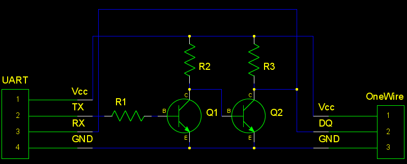
The standard way of reading 1-Wire sensors with a UART is to plop a pair of transistors and resistors on the Tx and Rx lines of the UART and connect them to the… one… wire on the 1-Wire device. [rawe]’s simplification of this is to get rid of the transistors and just plop a single 1N4148 diode in there.
This would of course be useless without the software to communicate with 1-Wire devices, and [rawe] has you covered there, too. There’s a small little command line tool that will talk to the usual 1-Wire temperature sensors. Both the circuit and the tool work with the most common USB to UART adapters.


A schottky diode would work even better.
You beat me to it! Diode would be way simpler and perform better.
you could also you a single npn transistor in common base configuration. base to Vcc via resistor, Tx to emitter, pull-up on collector
Oh! I often wondered how “1 wire” worked, I figured it send one side of the power rail and the signal on the “1wire” and a common ground. His web page shows it is 3 wires, separate power and data and ground.
It can use two wires, 1 ground and 1 power/data. It’s called parasitic power.
Data line is normally pulled high by master, so that connected device can power itself from it. When power is unavailable during transmission, device works from built-in capacitor.
I have occasionally seen problems when there is a diode on one of the UART lines., like 4148. For safety i would suggest swapping it for a Schottky like the trivial 1n5819.
@Brian Benchoff, out of curiosity, why does the article show the picture of the old and common version instead of the new one ?
It shows both. The new one is the thumbnail on hackaday.com, the old one is the title pic for hackaday.com/blog.
Finding images that can be cropped down to the right proportions is actually pretty hard for some of the posts on here.
Whats the statistics of those who go to .com or /blog? (if you can divulge) Im sure im not the only one thats changed all my bookmarks to /blog .
Did wonder the same thing about the picture! Will need to check the main page occationally lol
sam here. /blog all the time
+1, I never saw the ‘new’ circuit. I only saw the two transistor model and immediately thought “eh this is old and nothing new”
Yep, same here, and I as many have been reading a long time… 99.9% always on my android galaxy lite (well in the past more lowly droid smart phones) the “blog” displays perfectly on it, the main site… not so much.
My .02c
Blog all the time – home image only shows the latest blogs, can’t find the original any more. Shouldn’t have been very hard to do a composite image of old/new on blog if you were to take a little more time with the images. I’m just saying……
I’m on .com here (http://hackaday.com/2015/01/29/easier-uart-to-1-wire-interface/) and only see the ‘old’ version with transistors. The post only shows with 1 single image.
It would be nice to see an explanation of why the diode-based solution works – As a software person, I see a diode that just blocks all TX data, but that can’t be right…
1-Wire uses active-low logic. The bus is pulled high by default, and a device that wants to transmit a bit pulls the line low.
Putting a diode on each UART TX pin prevents signal conflicts where one device tries to hold the line high while another tries to pull it low. That’s important because UARTs don’t have a high impedance state where they can release the line so another device can use it. With the diodes, if device A’s TX pin is high and device B’s TX pin is low, the diode going to A will be reverse biased, cutting that high signal off from the rest of the bus.
A single pull-up resistor connected to the anodes of several diodes makes a distributed active-low OR gate. The voltage at the resistor is high only if all the pins on the other side of the diodes are high. If any single pin or combination of pins goes low, the voltage at the resistor also goes low, regardless of how many pins remain high.
The diode doesn’t block the TX data when it’s 0, it only blocks it when it’s 1. The ‘1’ is provided by the resistor, but it is weak enough that the chip can force a 0.
The wire rests at +V (logic HIGH)
When the TX line is high, no current passes through the diode, even if another device pulls the DATA line low.
When the TX line is low, and the data line is high, current flows through the diode, pulling the data line low.
Hmmm. Been recommending this approach for ages… and I didn’t even think of it.
https://electricimp.com/docs/resources/onewire/
Blue on black wires don’t show up as well as yellow/green on black. This makes your schematic harder to read. One color for symbols *and* wires would be a better choice.
Yes, geda has the worst default colors for a schematic program.
This is not new, This same diode/resistor arrangement has been used for years with a MAX232 IC to interface with OBD1 GM EFI. Even in the article it mentions using a MAX232 IC between the USB to TTL converter… There we use a 1N914 diode and 1K resistor. Although the resistor is in series with the TX pin (11) of the MAX232 IC, not being used for parasitic power supply.
I’ve used multiplexers for this.
Some microcontrollers allow open-drain outputs even when the IO pin is configured for a special function like a UART. In that case, you wouldn’t need a diode at all, just a pull-up resistor.
This solution works, but it eats up a serial port. The thing to remember is that the bit timing is critical, but the inter-bit/byte times are irrelevant as the master drives the timeslot. Solution: use a single port pin and the 1-Wire PDK.
http://www.maximintegrated.com/en/products/comms/one-wire/software-tools/public-domain-kit.html
If you want to go UART, you can plunk down $5 at Mouser and get a DS2480B. That handles all of the bus timing, etc.
Hi I want to write operation read operation not required how to modifie this circuit
I’m not really a hardware guy and am interfacing with a hot tub using the bus that the keypad connects to. I’ve got no documentation available to me, but here’s what I’ve figure out so far. Using a TTL to USB adapter I can receive and decode data as well as transmit to the device and have it respond. The problem I’m up against is that the tub seems to use a single wire for TX/RX and I am not sure if I can simply short the TX/RX pins on my adapter (I’m assuming this would work just fine) without causing any potential damage. Anyone out there that can help?
One wire implementation can be made often with the RX and TX lines set as open drain then connected internally. If the RX and TX lines can net be configured this way then the use of the 74LVC1G07GW,125 buffer line driver which is open drain. It can be used at 5 or 3.3 volt successfully . The biggest problem is the experience coders have no desire to code using UART which has associated buffers and DMA channel buffer that lower MCU load. The one wire which is maintained by Paul Stoffregen also has no desire to implement UART One Wire. Everyone says just use that library which has no associated buffers involved. Maxim has some code associated in the papers but no Arduino code available as does MicroE. MicroE unfortunately is for their platform only. Will anyone actually step up to the plate and code for UART One Wire after all these years and make the code available to unexperienced coders. I say very doubtful!