There have been quite a few DIY pick and place projects popping up recently, but most of them are limited to conceptual designs or just partially working prototypes. [Juha] wrote in to let us know about his project, LitePlacer, which is a fully functional DIY pick and place machine with working vision that can actually import BOMs and place parts as small as 0402 with pretty good accuracy.
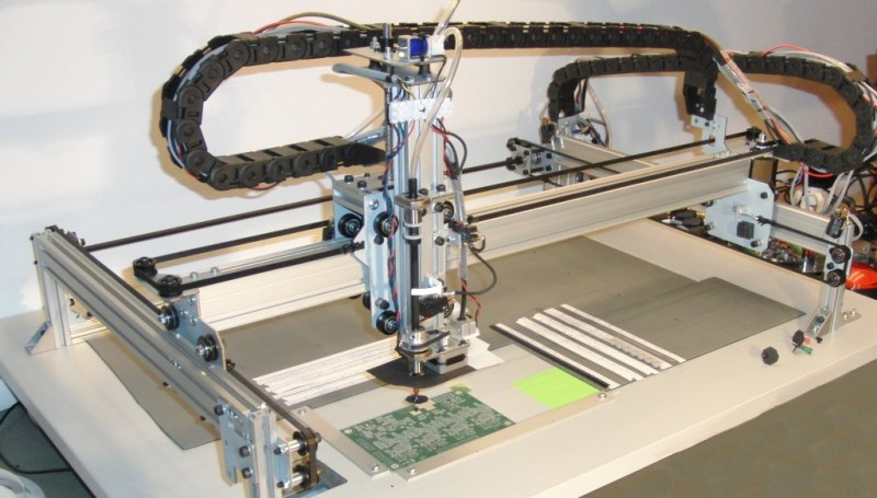
 While some other DIY pick and place setups we’ve featured use fairly exotic setups like delta bots, this machine is built around typical grooved bearings and extruded aluminum. The end effector includes a rotating vacuum tip and a camera mounted alongside the tip. The camera provides feedback for locating fiducials and for finding the position of parts. Instead of using feeders for his machine, [Juha] opted to pick parts directly from pieces of cut tape. While this might be inconvenient if you’re placing large quantities of a single part, it helps keep the design simple.
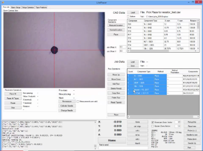
The software that runs the machine is pretty sophisticated. After a bit of configuration it’s able to import a BOM with X/Y information and start placing within seconds. It also uses the camera to calibrate the needle, measure the PCB using the fiducials, and pinpoint the location of cut tape sections.
If you want to build your own machine, [Juha] published detailed instructions that walk you through the entire assembly process. He’s also selling a kit of parts if you don’t want to source everything yourself. Check out the video after the break to see the machine import a BOM and place some parts (all the way down to 0402).


Simply awesome.
Looks like a shapoko style system. I like it! Thanks HAD!
Gotta love MakerSlide!
True, it is very much inspired by Shapeoko. (http://www.liteplacer.com/credits/)
We still want delta bot.
I don’t see any kind of a BOM on their site to try sourcing it myself.
Give me a week or two. I decided to announce it at this point although I had to make some minor changes from the beta to the real product. I will put the final BOM up and mechanical design files when I have put in the changes. In the meanwhile, if you want a BOM that is close but not quite correct, contact me!
This might have been clearer if the link on the downloads page (http://www.liteplacer.com/downloads/) would actually point to the note explaining this. Sorry about that, link is fixed now. (You don’t need to go and look, it is the same as above.)
Thank you! I participate at a maker space with a few electronics people, and we’ve been looking at our options. They DIY options are pretty sparse, there’s a lot of projects out there that aren’t complete or aren’t released.
I kind of wonder what the appeal of a home pick and place machine is. The amount of time spent getting this system ready to press ‘go’ would have had the PCB populated by hand. This system wouldn’t lend itself to processing more than a couple of board without having to redo all of the bits of tape (counting how many of each component, cutting it accordingly, peeling off the film etc.), so is the time really well spent? The only benefit I can think of is if somebody regularly makes one-off large PCBs with heaps of components, and even then, the machine configuration and maintenance seems like it would erode any benefit.
I built it because I needed it so badly myself. You can read the story here: http://www.liteplacer.com/about/the-story/
You need to get the parts out from your parts storage and lay them out on your table, no getting around that. The only difference is that when placing by hand you do that one by one, with the machine you put down all parts you want to place at the time. Once that is done, the time getting the system ready is a few seconds. You see all that is required (except turning the power switch and starting the program) on the video.
You are right, this system does not fit well if you want to do more than a couple of boards at a time, but I didn’t build it for that. The whole point of the machine is prototype builds and the almost zero setup. Production machines are faster but you need to process files, setup feeders etc., kind of like starting a printing press for one sheet of paper.
You also don’t need this machine if your board has five bypass capacitors, five pull-up resistors and an IC. You might _want it because it is fun to build and it is cool to have your own robot, but you don’t really _need it. But for developers doing the kind of stuff I do, this is a great help. I have no idea if that need is big enough to justify the effort I put in to this, it will be fun and exiting to find out! Ask me again in a year or so. :-)
Aah, 450 smd components. Yes I do believe I would make one of these too!
Your comment about your hand shaking after 1 hr with 2 hr still to go reminds me of the time I used to spend working on my motorcycle. Too low for standing, too tall for sitting, half-squat is the way to go. Until the legs start to wobble and the bike is still in pieces all over the ground. Once they start wobbling they don’t stop. On nose!
And might I say this is a very significant contribution to the DIY community. You’ve done a wonderful job.
This project is really a win in a lot of ways. I have been looking for a similar machine for some time now to meet my needs as a consultant, fearing the only way I could get one was to build it myself. The cheapest Prototype machine I have been able to find is one made by a chinese outfit. It costs upwards of about $5000 brand new, has very limited feeder options, and does not have any sort of vision system at all. I will be building one of these as soon as I get settled into my new workshop area… I also hope to be able to help make some contributions towards expanding its capabilities as well!
I build my FPGA board by hand for that HaD contest. I didn’t use solder paste, so I didn’t have the same time limits. I hand solder/reflow a part at a time. In my case my board took over a period of a day and a half as I was having a stiff neck after working 2-3 hours at a time. After that I had to take frequent break every 30-40 minutes until I couldn’t take it after 8 hours for the first day and spend another 3-4 hours to finish populating in the 2nd day.
For an initial proto like that going out to an assembly house can get very expensive. A DIY pick & place machine is near the top on my wish list.
Is the 0603 has worse alignment than the 0402 due to not centering the parts during pickup? May be a mirror on the table would be cheaper than having a 2nd facing up camera?
> Is the 0603 has worse alignment than the 0402 due to not centering the parts during pickup?
The resistors in my stock have looser pockets than 0402s. I don’t know if this is universally true or just because of the brand of resistors I’m using.
> May be a mirror on the table would be cheaper than having a 2nd facing up camera?
Maybe. The alignment of the optics would be a pain, though. (In general, there are lots of thing that could be done otherways; I did the machine like this.)
So I guess that there is no attempts to use the face up camera to correct for the *actual* component offset/rotation. This might be useful for loose parts or when the tape is not lined up properly.
Note that minor misalignments would be corrected during reflow for the light components.
Tape does not need to be aligned perfectly, the camera helps for this. What is not corrected is the loose pockets of a tape. That error is smaller than reflow self-alignment. For loose parts, the machine uses down camera. I don’t see a reason for the up camera to perform any better.
(I’ve done some work towards using the up camera for correction, but that is not ready for prime time.)
Geesh, I’m still working on building my first Reprap. Sometimes these posts make me feel so far behind!
Join the club! Ive been building one for the last 8 hours. The extruder is in reverse, but everything else is in order :)
Excellent!
Nice machine. Also nice that you edited out three minutes of boring video and did a short and to the point intro. Show, don’t tell. Same thing a good novel author does.
Very nice machine….Nice work! If you do not mind, a bit of out of topic question. The empty pcb you are working with looks very interesting. Nice solder mask, silkscreen…. seems professionally made.. but with the board without being cutted, I wonder if you also discovered a good method to silk and mask a pcb… Regards!
You missed the verbal explanation in the beginning of video: When testing the machine, using real circuit boards would be time and money consuming. That is just a laser printed image of a circuit board, not a real one. Good enough for optics and placement testing, but not very useful otherwise. :-)
Good point… English is not my native language as you can see.. I cannot understand very well people talking… (and often, youtube subtitles are a joke) so I did not turned it on…. But damn ! this print looks so real ! Thanks a lot and sorry for my misunderstanding…
thats nice and all but I need a machine that call pull the parts off asembled boards first.
Use a blowtorch, takes seconds.
Then go buy some new components :)
love it, also a fan of that style gui
Sexy!. Gotta have one… Perhaps with a check-box the placement can start the moment you identify the first part, as opposed to waiting for a complete list. Also, an Idea… To pick you need to suck, to place you need a slight puff. So what about a speaker as a air piston in stead of the pump. just put a sheet of mdf or plastic against the face of the speaker and feed a tube to the needle. if I had one I would test, for now, just sharing ideas.
What about a reprap adapter?
Speaker idea might work, the pump certainly does. :-) There is a slight puff because of the valve and pressure difference. In testing that is nice, but I’m not sure how necessary it really would be in real life, the paste is rather sticky anyway. But it is there.
Reprap adapter is not going to happen by me. But the software is out there now and mechanical files will be soon, I’d love to see somebody take a shot at it!
Really nice job with project and website!
The price has come in a little higher than I had hoped. Some ability to use reels, maybe just drag feed, and 0.5mm pitch placement would be pretty useful for me, but I realise not everything can be done and keep the price down.
As far as I know, there is actually nothing else on the market at this sort of price. I’m not sure if that means there is not much demand for PnP at the hobby level, or whether it’s just that no one has created one at a price people can afford.
I’ve been trying to put together my own machine, but mechanical side is not really my strong point.
Awesome. But how did it not eat the 0402s? They look as though they could get sucked up the needle.
I too noticed that it looks like that, but didn’t bother to re-shoot the video. :-) The needle inner diameter is about the same than 0402s are wide, but length-wise there is room to spare. Adding the needle wall thickness, it indeed does look a bit iffy, although it really isn’t.