After what we’re sure is several dozen screw-ups or at the very least a lot of wasted hours, [Chris] has gotten around to building a very precise microscope camera mount for zeroing out his CNC machine.
If you need to mill a few bits out of a sheet of metal or plastic, it’s important to know exactly where you’re cutting. A CNC machine can take care of the relative positioning, but if you already have half your holes drilled, you also need absolute positioning. This means placing the work piece exactly where you want to cut, or failing that, zeroing the machine to a predefined point on the piece.
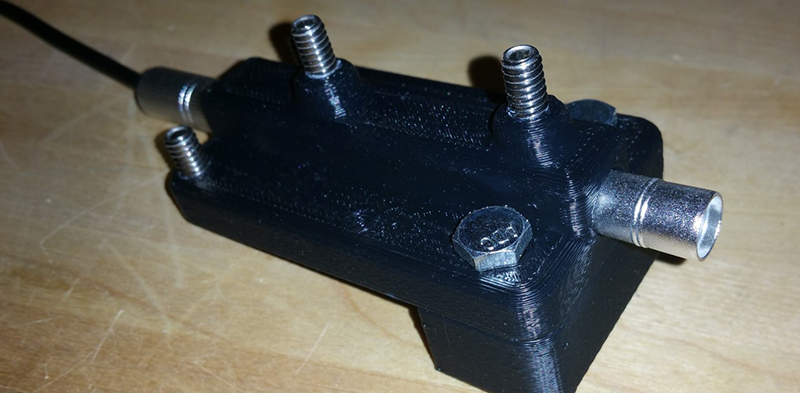
[Chris] is accomplishing this with a pen-shaped USB microscope. With a 3D printed mount and a few magnets, this camera can clip right on to the machine, and with the camera interface in Mach3, it’s pretty easy to zero out the mill to within a thousandth of an inch.
There’s a video demo of the camera in action below, but there’s a lot more CNC mods on [Chris]’ website. There’s custom 3D printed vacuum nozzles, and a lot of work on a small desktop Grizzly mill.


His entire website seems to be a collection of simple genius!
A much easier way to zero your stage is using a conductive contact switch. Ground your reference point and pull up your sensing pin and attach it to the relevant portion of your stage. When the circuit is closed by contact, your sensing pin is pulled down. I use this for my CNC machine and even have built in g-codes to execute automatically finding the reference points. It can go down and find the PCB, and then go in the X or Y direction until it finds the reference hole. It then maps the edge of the hole and finds the center. It is very accurate and repeatable.
Let it run in a feedback loop and you’ll get a big ass (unprecise) STM.
Only good if your milling a conductive material
Putting a USB microscope on your three-axis machine would be handy for checking soldering of PCBs too.
Another issue usually missed-the possibility of creating an optical Computerized Measurement Machine (CMM).
Having worked for a few years in Metrology (measurement science) I can attest what a a ridiculously handy thing a good CMM is in a production environment-not just for QC checks, but it makes reverse-engineering a snap. Anything can be measured to about a 5 micron accuracy-but with a few caveats:
The part must be squeaky clean and dry.
Contact probes are very expensive, and you’ll need many sizes and shapes.
Like a CNC tool-you’re limited to the machine’s volume, and a bit extra if it’s okay for a part to stick out and not interfere with gantry travel.
The machines I worked on were made by Aberlink (www.aberlink.com/) and relied on physical contact with a sapphire contact tip. The next generation machines (never got to play with one) used the same gantry setup-but a high-resolution camera to detect landmarks. The best part was that it went from a contact situation (having to physically probe something) to just imaging it, and you could even use monochromatic light sources to improve resolution and accuracy. In situ images were a snap.
CNC know-nothing here, so please pardon the stupid question. What would be a real-life example where one would have a part drilled first and then milled?
Well sometime you need to modify a part that has already been milled out. You need to pick a reference point on the part and that is usually some edge or corner in the part. Other times it is a already drilled hole, whatever is easiest up set your origin.
To extend the answer from [Jim], sometimes it is necessary to make different steps where you have to move your part (think milling the backside), or repairing parts.
Loving that SuperEyes GUI
Edge-finder anyone? A $10,- instrument. <5-10 micrometer repeatability. (Its analog)
Was going to mention an edge finder but you beat me to it.
Edge finder would locate the actual tool as well instead of an arbitrarily positioned camera.
Oh, XY zeroing. Going by the web site, he does use a touch plate for Z.
I don’t see where you get that position correct when there’s no apparent registration for the camera mount so that its location is sufficiently repeatable for CNC work.
I am just guessing here, but I assume that he places it securely (with the magnets), and then adjusts X and Y once. After that, he doesn’t move it. If it does get bumped, yes, he would have to go through zeroing X & Y again; but that would have to be done anyway, since the mount is plastic. You wouldn’t be able to get micron-level accuracy because of differing coefficients of thermal expansion, but if it is in a temperate-stable shop, you may be able to get close.
Depending on the overall condition of the mill in question, he might be capable of accuracy at least equal to the mill. And at the end of the day, that is what it really comes down to. IMMV.
A dry erase marker works really well too! http://m.instructables.com/id/Easy-edge-finding-0001-0025um-on-the-Othermill/step4/Index-the-corner/
As JRDM said, you need to be sure you can have a fixed, repeatable known offset between the camera and the spindle. I’d recommend some grub screws to help align the camera exactly parallel with the spindle otherwise this will vary with Z height. These cameras don’t necessarily have the optics exactly aligned with the outside casing.
I did something very similar but mounting the camera (on eBay as an endoscope) in the chuck. On my mill it seemed easier to put in in the spindle than have a known offset beside it. Grub screws for alignnment.
https://0xfred.wordpress.com/2014/02/13/cnc-mill-alignment-camera-version-1-0/
The idea was to line up my etched PCBs so they could be drilled and milled. It worked reasonably well, but still not good enough for tiny 0.7mm vias across the whole PCB. Not sure why but have a few ideas.