
Logic Noise is an exploration of building raw synthesizers with CMOS logic chips. This session, we’ll tackle things like bells, gongs, cymbals and yes, cowbells that have a high degree of non-harmonically related content in them.
Metallic Sounds: The XOR
I use the term “Non-harmonic” in the sense that the frequencies that compose the sound aren’t even integer multiples of some fundamental pitch as is the case with a guitar string or even our square waves. To make these metallic sounds, we’re going to need to mess things up a little bit, and the logic function we’re introducing today to do it is the exclusive-or (XOR).
An XOR logic gate has two inputs and it outputs a high voltage when one, and only one, of its inputs is at the high voltage level. When both inputs are low or both inputs are high, the output of the XOR is low. How does this help us in our quest for non-harmonic content? It turns out that the XOR logic function is the digital version of a frequency mixer. (Radio freaks, take note!)
Ideal frequency mixers take two input frequencies and output the sum and difference of the two input frequencies. If you pipe in 155 Hz and 200 Hz, for example, you’ll get out the difference at 45 Hz and the sum at 355 Hz.
Because we’re using square waves and an XOR instead of an ideal mixer, we’ll also get other bizarre values like 2*155 – 200 = 110 Hz and 2*200 – 155 = 245 Hz, etc. All said, the point is that we get out a bunch of frequencies that aren’t evenly divisible by one another, and this can make for good metallic sounds. (And Dalek voices, for what it’s worth.)
The 4070: Quad XOR
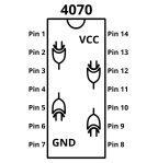
Which brings us to our logic chip du jour. The 4070 is another 14-pin wonder, just like the 40106 and the 4069UB and the power and ground pins are in the same places. Since an XOR gate is a three-pin deal, with two inputs and one output, only four XORs fit on the 14-pin chip instead of six inverters.
By now, you’re entirely used to the 4000-series logic chips, so there’s not much more to say. This is a great chip to add sonic mayhem very easily to your projects.
Frequency Modulation with XOR: More Cowbell!
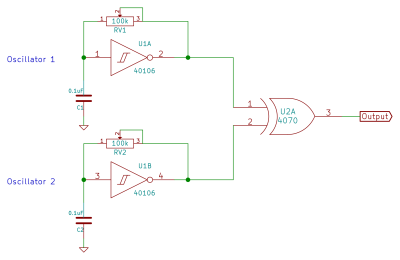 Let’s make some metallic noise. The first step is to mix two oscillators together. Whip up two variable-frequency oscillators on the 40106 as we’ve done now each time, and have a listen to each individually. Now connect each output to the inputs of one gate of an XOR in the 4070. As promised, the resulting waveform is a lot more complex than either of the two inputs.
Now tune them around against each other and listen to all the strange frequency components created as the sums and differences slide in and out. Cool, no? Here’s a bonus video that you can skip, but that demonstrates what’s going on with the frequency mixing.
Two-diode VCA
After a couple of minutes playing around, you’ll start to realize that this sounds nothing like a cowbell. We’ll need to shape the volume of the sound in time to get anywhere, and this means another step in the direction of “traditional” synthesizers. We’ll build up a ghetto voltage-controlled amplifier (VCA) and drive it with the world’s simplest envelope generator.
An active VCA takes its input signal and either amplifies or attenuates it depending on the control voltage (CV) applied on another input. When the control voltage is high, more of the sound gets through, and when the CV is zero, the output is ideally silent. Building a general-purpose VCA is a bit out of scope for our needs, so let’s just cobble something together with a few diodes.
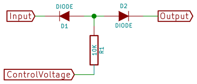
This circuit works by cheating, and works best with digital logic signals like what we’ve got. When the input from the XOR is low, diode D1 conducts in its forward direction and all of the control voltage signal is “eaten up”, sunk into the output of the XOR chip.
Conversely, when the XOR is high, diode D1 is reverse-biased and blocks the CV, leaving it nowhere to go except through diode D2 and out to our amplifier. The resistor needs to be large enough that the XOR can sink all of its current, but otherwise the size is non-critical.
 Notice what’s happened here. The voltage at the output is no longer the GND to VCC of our logic circuit, but instead ranges only from GND to the control voltage (minus a diode drop). So if we want to make a quieter version of the XOR input, we just lower the control voltage. It’s a simple voltage controlled attenuator. Now we just need to create a voltage signal that’s got something like the amplitude contour of a cowbell.
Remember how we converted square waves into trigger pulses by adding a series capacitor? The resulting voltage had this steep rise and exponential trail-off.
If we add in another capacitor, we can lengthen out the decay. And then while we’re at it, we can add in a potentiometer to control the rate of that decay.
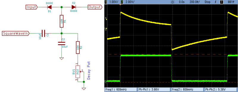
Capacitor C1 converts the square wave into a pulse and charges up C2 very quickly, applying the positive voltage to the input of our VCA. The charge on C2 drains out through the variable decay potentiometer.
This simple circuit actually works well, but has one shortcoming. For long decay times, as illustrated above, the decay gets cut off when the control square wave goes low. If you only want short percussive hits, the simple circuit is enough. If you’d also like longer decays, you’ll need to add a couple diodes to chop off the negative part of the control voltage spikes.
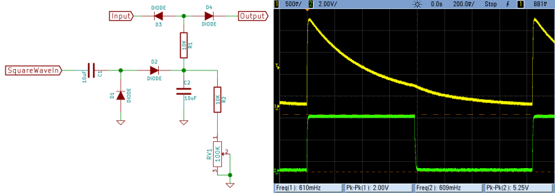
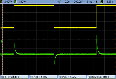
Now that only periodic positive spikes are getting though to our decay capacitor, we have a nice variable-rate exponential decay voltage envelope. Here’s how it looks on the scope (with some extra capacitance slowing down the attack — 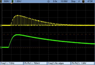 it might have been connected to the laptop soundcard). You can clearly see the control-voltage envelope chopped up by the diode action and the XOR’s output.
Putting the XOR frequency-modulated sounds through the two-diode VCA that’s driven by our quick and dirty envelope generator gets us a percussive metal sound. But it it cowbell? We still have to tune the oscillators up.
The classic, love-it-or-hate-it, cowbell sound of the 1980’s has to be the Roland TR-808. And if you look through the 808 service manual (PDF download) you’ll see that it uses two square waves from a 40106 chip simply mixed together. We’re improving on that by XORing, but we can still learn a bit from Roland. In particular, they tune their oscillators to 540 Hz and 800 Hz.
Because we’re XORing two oscillators together, our peaks come in at the sum and difference frequencies. This means that we’ve got to solve X + Y = 800 and X – Y = 540. Grab pencil and paper, or just believe me that you’ll want to tune up the individual square wave oscillators to 130 and 670 Hz respectively. At least, to get something like that classic cheesy cowbell sound.
Amplification Aside
We’ve been trying to stick to the use of purely CMOS logic chips here, but this session we broke down and used a transistor. The reason is that the audio input on our laptop insists on a bipolar, centered audio signal. In contrast, the output of our “VCA” sits mainly at zero volts with very short peaks up around one volt. The input capacitor in the laptop is charging up and blocking the VCA’s diode output. Boo!
Indeed, we can’t use our old tricks with the 4069UB as an amplifier here either. The 4069UB works great for signals that are centered around the mid-rail voltage, but distorts near either GND or VCC. Unfortunately, we’d like our quiet drum sounds to taper off to zero volts rather than the mid-rail, so we’ll have to use something else to buffer our audio with.
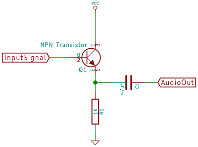
The solution is to buffer the output with something suited to this unipolar signal, and the simplest solution is a plain-vanilla NPN transistor hooked up as a common-emitter amplifier common-collector amplifier. This configuration is a very useful analog buffer circuit; it puts out almost the same voltage as the input, but draws directly from the VCC rail and will certainly handle any sound card’s input capacitor. We used a 2N3904, but a 2N2222 or BC548 or whatever will work just fine.
Cymbals
Cymbals and similar metallic percussion instruments were pretty tricky to synthesize in the early days of drum machines. Until the LinnDrum introduced sampled cymbals, most just used a shaped burst of white noise. The aforementioned TR-808 used six 40106 oscillators linearly mixed together to approximate white noise. Again, we’ll improve on that by running it all through XORs with the result being somewhere between many oscillators and pure noise depending on how you set the oscillators up.
The inspiration for this circuit is the fantastic Synbal project (schematic in PDF) from “Electronics & Music Maker” magazine in 1983. It’s a much more complicated affair than what we’re doing here, but if you look at the left-hand side of the schematic, that’s the core. (If you’re copying the Synbal’s fixed frequencies for the oscillators, note that he uses 0.01 uF capacitors and we use 0.1 uF caps. Divide the feedback resistors by ten accordingly.)
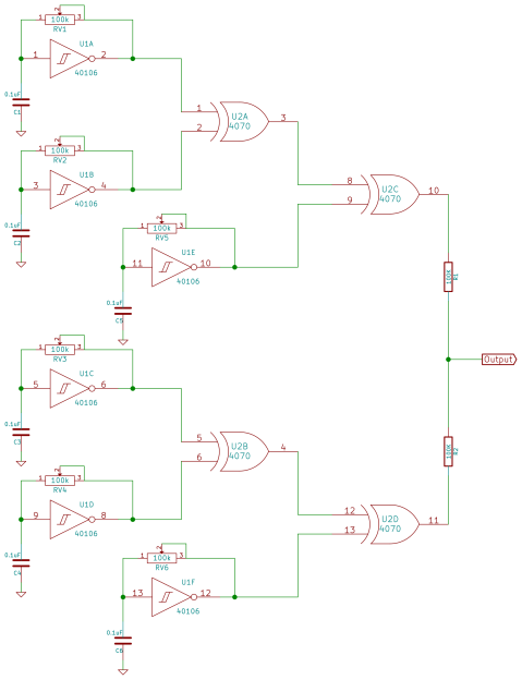 The trick to the cymbal circuit is making a lot of oscillators. We’ll hook up six of them, finally fully fill our 40106 chip. Then combine any pair in an XOR, take the output of that XOR and combine it with another oscillator. You’ve now got a complex oscillator that’s used up three 40106 oscillators and two XOR gates. Repeat this with the remaining oscillators and XOR gates and you’re nearly done. Connect the final two XOR outs through resistors to the output.
As with the cowbell circuit, this circuit can be made to sound “realistic” by picking the different component frequencies just right and tweaking the decay. We think that it makes a pretty decent hi-hat sound with a couple of the oscillators pitched high (1 kHz and up). On the other hand, if you’re into noise music you can skip the VCA altogether and tune the oscillators to similar, low frequencies. You get a vaguely metallic, almost rhythmic machine drone. Not to be missed.
Extensions
We’ve snuck it in under the guise of making a cowbell sound, but the quick-and-dirty VCA here is also useful for modulating most of the synth voices we made in the first few sessions. We went for a percussive attack by using a capacitor to couple the driving square wave to the VCA, but there’s no reason not to use a variable resistor in its place to charge up the capacitor more slowly. If you do this, note that the attack and decay potentiometers will interact, so it’s a little quirky, but what do you want for two diodes anyway? Also note that any other way you can think of delivering an interesting voltage to the junction of the two diodes is fair game.
The XOR-as-frequency-mixer technique is pretty great, but you can also get a lot of mileage by using the XOR as a logic chip. Combining different divided-down clock outputs (from a 4040, say) with XORs makes interesting sub-patterns, for instance. And we’ll get more use out of the XORs in two sessions when they’re coupled with shift registers.
Next Session
We’ve got a whole lot of possibilities by now. We’ve got some good, and some freaky, percussion voices. We’ve got a bunch of synthesizer sounds, and if you recall back to the 4051, we’ve got a good way to modulate them by switching different resistors in and out. It’s time to start integrating some of this stuff.
If you’re following along, your homework is to build up permanent (or at least quasi-permanent) versions of a couple of these circuits, and to get your hands on at least two 4017 decade counter chips. Because next week we’ll be making drum patterns and introducing yet one more way to make music.


Great series, looking forward to the next one!
Great Series, looking forward to the next installment!
Tangerine Dream fan…
You amplifier is common-collector ( https://en.wikipedia.org/wiki/Common_collector ) commonly referred to as emitter follower, not common-emitter. Common emitter takes its ( phase inverted ) output from the collector and typically gives voltage gain.
Doh! Thanks. Fixed.
On the amp schematic you have the 1k coming from the emitter to ground but on your bread board it looks like you have the 1k going to power?
Sounds like a crude form of a ring modulator.
It would be interesting to try Dalek voice modulation (Dr Who) using this circuit, to compare it with the ring modulator originally used for those vocal effects. I did a similar thing using DSP ring buffers back in the ISA bus sound card days (one particular sound card had a programmable DSP). Fond memories doing “alien robot voices”, there…
Exactly! An XOR is like a ring mod for digital signals — they’re both frequency mixers!
And on that topic: http://www.cgs.synth.net/modules/cgsrr.html, a diode-and-transformer ring modulator, works great with our relatively high voltage CMOS signals — run all inputs and the output through large (10uF+) capacitors to remove the voltage offset.
FWIW the diode/transformer circuit is the ring mod actually used by the BBC for the Dalek voice. I read that they’d tried other things, but that they like the non-linear distortion that one gets from diodes. It’s not apparent with square waves, but it does sound nice on “normal” audio.
And I so wanted to get a XOR CMOS Dalek voice going for the project. You can’t imagine. Hence the throwaway sentence.
Here’s my half-baked idea: take audio input, drive it to the rails to with a fuzz effect (heck, the one we made with the 4069?), then XOR that with a ~20Hz tone or whatever those wacky BBC folks did. I’m 99.9% sure you could make it work, though I have no idea if it would sound good.
Here’s another from the half-bakery, fresh out of the oven, that should work even if you insist on analog signals. Make an inverted copy of the signal (one stage of the 4069 with unity gain?) and switch back and forth between the inverted and non-inverted signal using two channels from our 4051 circuit, or a 4066 digital switch. This is the principle behind the Gilbert Cell mixer (https://en.wikipedia.org/wiki/Gilbert_cell), and there’s a few radio designs doing this with CMOS, though my Interwebs searching is failing me ATM.
Bam! Three more mixers. None as easy to implement as the humble XOR. :)
If someone makes a 1-bit Dalek, write it up and we’ll toss it in the blog.
It’s possible if you convert the voice input to a Delta-Sigma stream. The XOR function closely resembles a 4-quadrant multiplier (albeit noisy) if you XOR two streams then put the output through a low-pass filter. The Delta-Sigma ADC doesn’t have to be complicated either. http://kaput.homeunix.org/~thrashbarg/deltasigma.png (the pull-up resistor is used because the op-amp should be a comparator)
If you have two ADC’s, one driven by voice and the other by a low frequency sine wave, then XOR them and filter the output, you’ll get the Dalek voice.
Good article but the sounds are pretty awful of course, and it reminded me of tuning to find signals on SDR. So that made me think, what if you made a very simple basic AM receiver tuned to one of those stations that constantly sends out tones and use that as an impromptu oscillator/tone generator? That would be an interesting way to go.
pretty awful can be insanely beautiful when it comes to sound…:-)
Excellent article indeed
wow… awesome
Love these articles, they keep getting better!
To quote the Beastie Boys: “Nothing sounds quite like an 8 0 8.”
What would one google to research doing this sort of thing with DSP in an ARM of some type?
Elliot, I’m enjoying this series a lot, I’m following the articles from the start and I’m just waiting the next one, I want to do a modular simple synth for my kid (5 years old), until now, he did’t like the noise too much, but I’m enjoying a lot, and I’m using a lot of IC that I bought when I started in electronics.
Just a question, I’m using a LM386 as amplifier, which works ok, are you thinking in doing an article for this part? do you suggest other IC? class A?, class B?, class AB ? I read a lot of articles of Elliot Sound Products, which are great, but I’m thinking in a simple project as amplifier a not a discrete power hungry monster. Any suggestion is welcome. Thanks again.
The LM386 is often totally sufficient. Just make sure you’ve got adequate buffering caps all around and add in the zoebel (resistor + cap) damper network on the output. I bought a tube of something ridiculous like 50 of them from a surplus discounter ages ago, and I’m still working my way through it. I use them all the time for the quick-and-dirty. That said, the LM386 is a bit noisy and a power hog.
A chip with a bridge-tied-load output (I like the TDA7052A/AT) works better if you’re using batteries, and doesn’t really cost all that much more. The TDA7052A series is particularly neat in that it uses a DC voltage-level input to control volume. Just follow the design in the data sheet.
Finally, for desktop use it’s hard to beat a scrounged/free powered computer speaker. Having a nice housing built around the speaker makes a huge difference in the sound, you get a volume knob already built in, and you can often find these free / lying around. For mine, I clipped the stereo-jack input and soldered alligator clips (left, right, ground) in its place.
http://www.musicfromouterspace.com/index.php?CATPARTNO=&PROJARG=MINIAMPANDMIXER%2FMINIAMPANDMIXER.php&MAINTAB=SYNTHDIY&SONGID=NONE&VPW=1670&VPH=809
simple 9V amplifier with lm386
Thanks Daan, as I asked Elliot, I was already using a LM386, but I would like a little more power available, and I wasn’t at all sure of the sound quality of the chip, but I will bookmark the url you shared, some of the circuits seems to improve over the standar AppNote. But I’ll have to look it deeper at home. I was considering a couple of 8′ fullrangers that I already have, and possibly a couple of twitters doing bi-amping , and I tought that a least (four) TDA2050 would be needed, but I was wondering if newer chips could be more efficient and have a better sound quality. But, thinking a little, probably, 20 or 30 watts of porwer is overkilling for my 5 y.o. kid. :)
So freaking cool! Thanks for posting this stuff– it’s truly a revelation. So many sounds from a handful of components! I built this (with some tweaks) and added it to my DIY modular. Here’s a video of of the noise going through a low pass gate triggered by Ableton Live: https://www.youtube.com/watch?v=AoQc1y9jgi8
love the articles on this site, they give me a lot of inspiration for my own lunetta-project.
the strange thing, however, i only get the vca/envelope generator working when i leave out the diode before the output (first two images d2, third image d4). i don’t get it. but without that diode the vca seems to do it just fine.
What kind of diode did you use I cant seem to get this to work?
Hi Elliot! love your logic noise series, extremely easy circuits for instant application. I’m thinking of using this ideas for some noisy project i have in mind. Despite this circuits works by error, i find really interesting on analyze how it works. I don’t really understand how D1 and D2 chops negative part of the signal in that circuit. Is it that D1 works as a voltage clipper? or is it that D2 function as a voltage rectifier? I’m really confused about this cause i know that circuit won’t work without any of this diodes. Any reply will help. Thanks!
You absolutely need one of the diodes — the one to the logic-level audio signal. The other one just makes the circuit work better. Let’s look at the left-hand diode first. (D1 in that first schematic.)
Think of the analog control voltage, which makes the volume envelope here, coming up through that resistor to the junction of the two diodes. If the logic audio voltage coming in from the left is high, the diode blocks, and the output of the circuit is just the control voltage. When the logic audio input is low, that diode conducts, and pulls the voltage at the junction down to one diode-drop above 0V.
The other diode (D2) just puts that same diode drop on the output signal, so that the output ranges from 0V to the control voltage – one diode drop. If you get rid of it, there will be a small signal coming out even when the control voltage is at 0V.
Finally, this circuit is really rough. :) There’s a really clever solution using 4066 analog switches instead of essentially diode switches in this thread: http://files.electro-music.com/forum/viewtopic.php?highlight=diode+vca&t=23960 I would have done that if this weren’t meant to be a super-intro series.
But _do_ check out the Electro-music Lunetta forum if you’re interested in this stuff. I planned to do a big bibliography post as part of the Logic Noise series, but it never happened.
I also gave a Logic Noise talk/demo at Belgrade 2018: https://www.youtube.com/watch?v=yvuRexTgY2E
And I just found out that the slides are still on-line, and they have references for individual circuits as well. https://littlehacks.org/2018_logic_noise/ Hah. Internet never forgets.
I know this is a bit of an old post at this point, but thanks for this great resource! Really well made and easy to follow.
I’m working on a freeform circuitry/Peter Vogel-inspired CMOS sculpture right now, and this is just the type of noise generator I needed. I’ve never seen such a simple VCA/envelope design before! I don’t have any 4070s on hand atm, so I might try a little prototyping using NAND gates instead of XOR just to see what happens. It will be interesting to hear the difference between the two.