While [Drew] was in China for the Dangerous Prototypes Hacker Camp, he picked up some very bright, very shiny, and very cheap LED strips. They’re 5 meter “5050” 12V strips with 20 LEDs per meter for about $15 a spool. A good deal, you might think until you look at the datasheet for the controller. If you want an example of how not to document something, this is it.
A normal person would balk at the documentation, whereas [Drew] decided to play around with these strips. He figured out how to control them, and his efforts will surely help hundreds in search of bright, shiny, glowy things.
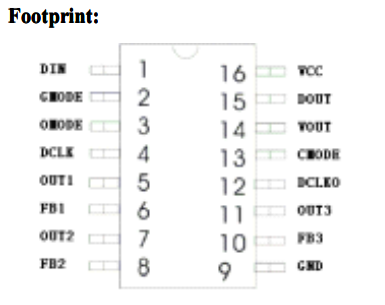
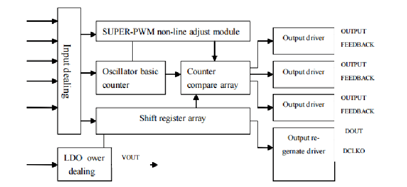
The datasheet for the LPD6803 controller in this strip – available from Adafruit here – is hilarious. The chip takes in clocked data in the order of Green, Red, and Blue. If anyone can explain why it’s not RGB, please do so. Choice phrasing includes, “VOUT is saturation voltage of the output polar to the grand” and “it is important to which later chip built-in PLL regernate circuit can work in gear.” Apparently the word ‘color’ means ‘gray’ in whatever dialect this datasheet was translated into.
Despite this Hackaday-quality grammar, [Drew] somehow figured out how to control this LED strip. He ended up driving it with an LPC1768 Mbed microcontroller and made a demo program with a few simple animations. You can see a video of that below.


>If anyone can explain why it’s not RGB, please do so.
Most likely because it was easier to layout the stripes in that way. Note that WS2812 also has GRB colour order, due to the way the dies are arranged in the LED package.
Cheap but still adds up rapidly to over $20K to build a 640×480 display. Even if the LEDs cost gets down to a penny per that’s still $3072. At 1/8 cent the cost finally gets down below $400 and into the reach of people with thinner wallets.
i dream of the day
..but you’d still need a lot of power supplies…
Yeah…at maximum brightness you’d need about 18,000 amps at 5V. It would be a 92 kilowatt display, 32 feet wide and 24 feet tall using the 60px/m strips.
You don’t necessarily need 640×480, depends what it’s for. If you did build that resolution, it’d be 32 metres wide by 24 high. You’d need a decent-sized aircraft hangar to watch it in.
If you want hi-res, and presumably you want it to fit into a room you own, use something else, use a projector. Making these ribbons into video displays is a massive hack, tho it’s been done. But you might want to shrink the resolution by 10, 64×48 and it’d still be taller than you are.
Here’s one: http://ws2811softdisplay.blogspot.ca/
Nowhere near 640 x 480 but still rather impressive – scaling up should be trivial.
As an aside, look what one can do with a cheap soldering iron that hasn’t been cleaned since TV was invented.
LED strips have poor brightness matching, poor heatsinking, and short lifetime. Inefficient too. Each LED color has a different forward voltage, from 1.8V for red up to 3.2V for green. But it’s all powered by 12V. So guess how they regulate voltages/currents and keep these cheap? Resistively, which also adds to the heat issue. PWM is also used, but doesn’t help as much as one might think, since LED output doesn’t scale linearly with current. Driving a LED at 200% rated current at 50% duty cycle doesn’t produce as much light as continuous drive at 100% rated current; you might have to use 225-250% current and 50% duty cycle for an exact match.
Folks have used LED strips for room or aquarium illumination, and often find them to lose 50% of their brightness after a year. I doubt it’s worth building a 640×480 display from them at any price. Even at $400, unless it’s just a toy rather than a serious display for computing or watching videos.
Not (necessarily) related to the above rant, I notice the LEDs at the right-bottom of the video (by the adjustable power supply) aren’t following the color pattern of the rest of the strip, in a way that looks unintentional. I don’t see mention of this, so what’s going on here? Still some timing issues to work out? Defective strip? Metal case of power supply shorting the strip, or adding a stray capacitance that mucks up the data signal?
I think you’re confusing 2 types of strips. Accent strips are usually 12V non-programmable and dies are wired 3 in series then those series’ in parallel and use resistors to “regulate” the current in each set of 3… and the remaining drop of ~3V at 20mA/colour is not so bad on the G&B. I’ve had 10m of the 60/m type lining my room ceiling for a few years without any noticed dimming, but they’re only on for 4-6 hours a day . I’ve never seen a 5V variety of these.
Programmable 5V strips use constant current capable ICs (that I’ve seen) and usually 0 resistors. 12V versions tend to be the same 3-in-series with sometimes 1 resistor just for the red. Colour linearity is way off, you are right, but easily compensated in software.
You can get 5v non-programmable strips, they’re pretty rare though (probably excess from someones custom run). I’ve only seen single colour versions..
5v makes more sense when you’re controlling current via resistors, plus you can power them from USB. But 12v it is.
There is one detail I wasn’t clear on and I skipped over (related to having 3-in-series), but otherwise I think I’m not as confused as I think you think I am. ;) Notice I never used the word “resistor”, I said “resistively”, and chose that very deliberately. Because the constant current function of the ICs is inductorless, it cannot function as an efficient switching current regulator. Instead it has to use a transistor driven in the linear region, functioning as an electronically variable resistor. That wastes power and generates heat, just like the separate SMD resistors you’re counting.
Also, for color linearity issues of the type where driving the entire strip at 100% each of R/G/B doesn’t produce perfect white, you’re right, that’s easily compensated for in software. What I’m more concerned about is where (for example) out of the red LED chips, some will produce more light in response to 10mA, and others less, due to normal manufacturing differences. For quality LEDs, each is tested, measured, and “binned” so that if you order from a single bin, these differences will be minimal. But these strips use cheap LEDs with relaxed quality control. It’s not very noticeable in a linear strip, but put the LEDs in two dimensions for a display, and it becomes more noticeable when displaying areas of (what should be) uniform color. That too can be corrected in software, for [Galane]’s example 640x480xRGB display you’ll need a table with 921,600 correction values in addition to the global correction. Which will take some additional processing power, that’s the easy part. Measuring light output for all those LEDs to generate the table is the hard part. You can get clever with a camera and try to do the entire display at once, but it’s still not exactly easy.
When I took the video I had the first 3 pixels sets to red, green, blue for testing. It’s not in the demo code I posted. No timing issues
LPD6803 is the same as controller D705, datasheet here:
http://www.deskontrol.net/descargas/datasheets/D705.pdf
maybe that some help to anyone interested.
Here is some color organ Arduino/Processing project for that kind of strips, all code available:
https://www.youtube.com/watch?v=E5r9btOSS_o
NOW you tell him!
Even knowing what data to send, and how to send it, is gonna be a big help.
BRG ordering: Back in the day, many computers (like the Heath/Zenith 100’s was one IIRC) used this for bitmapped graphics. One reason given, though not the only one, was that this put green, the color to which the eye is most sensitive, and the common color for text back in the day, at the high order end of the bit sequence, being convenient when the output could be to either a color or a mono monitor. I suspect this was a post-hoc reason for an essentially arbitrary choice. This weighting is also reflected in the mapping used for NTSC, with green being most heavily weighted in the Y (luminance) component, at 0.58-ish.
I’ve bumped into the same datasheet and the only thing I learned was that its translation was outrageous, but so it is for other stuff that comes from non-english countries.
I actually find it entertaining trying to decipher them :D
about the “gray”, it’s common parlance to define the full range of intensity of a single PWM channel as grayscale, maybe that’s the reason.
if you think about an 8bit PWM (0>255) it makes perfect sense to define it as a “grayscale”, because you’re effectively controlling a signal, not a color.
+1. This chip doesn’t have pins declared as red/green/blue, nor does it need to. It merely has three channels, what you decide to hook them up to is your business. Though it will most commonly be RGB LEDs, you could use one chip to separately control the intensity of three white LEDs. Or for a grow light, royal blue/633nm red/660nm deep red.
And as for why this strip was set up as GRB instead of RGB, I agree with [cpldcpu]. Strictly a practical decision based on the shortest and most direct traces.
the reason it is not rgb has to do with manufactoring qc issues..
some strips are rgb, some are grb and other variations… Whenever I get a 6803/705 based strip from china (EVEN if from the same provider) my first step is to map out the mapping of 1st/2nd/3rd “byte” to r g b. of course byte might be the wrong word since they are 5 bits and each element is set with 2 bytes of data
I’m quite puzzled as to how the R G B ordering is altered due to QC issues.
“Despite this Hackaday-quality grammar…” hahaha
That my friends, is what is known as, “a pre-emptive strike”.
E.P.I.C.
I snorted some Tea up my nose, reading that.
Jesus, why would anyone willingly go back to using LPD6803’s – 5-bit color, shitty control structure, etc….? (They were the second led chipset I added support for to FastSPI_LED back in 2010 (after the HL1606) – I dropped support for them when re-architecting it into FastLED a few years ago because I found that the LPD8063’s required strobing the clock line constantly to drive the PWM clock (and I wanted to ditch background timers) – probably because the strip manufacturers weren’t bothering to to set CMODE).