Before we begin, we must begin with an obligatory disclaimer: handling mains voltage can be very dangerous. Do not do so unless you are qualified! You could burn your house down. (Without the lemons.) That being said, [TJ] has created an interesting dev board for controlling mains voltage over WiFi with the now-ubiquitous ESP8266 module. At only 50mm x 25mm, it is easily small enough to fit inside a junction box!
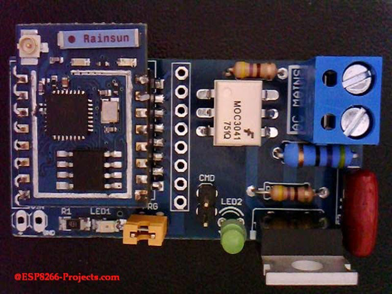
Called the MPSMv2, the core of the project is the ESP8266 module. The dev board itself can support anything with GPIO pins, whether it’s an Arudino, Raspberry Pi, or anything else with those features. Flashing the NodeMCU firmware is pretty much all that needs to be done in order to get the device up and running, and once you get the device connected to your WiFi you’ll be able to control whatever appliances you want.
The device uses a triac to do the switching, and is optically isolated from mains. Be sure to check out the video after the break to see the device in action. All in all, this could be a great way to get started with home automation, or maybe just do something simple like build a timer for your floor lamp. Anything is possible!


Can you “easily small enough to fit inside a junction box!” this and still meet US code?
Arudino? HAD fail :D
Tagged arduino, dev, ESP8266, NodeMCU, raspberry pi, wifi
Nah, they’re just creating the latest OpenSource platform as Arduino LCC, Arduino iso, Arduino Inc and Arduino & Co. fight over which is the real Shady.
Opto-isolated TRIAC is fine and dandy, but there is no fuse, so if you overload it, you have a cooking TRIAC in your junction box …
Exactly, sometimes less of a compact form factor makes a better product overall.
Snubber circuit is a nice touch tough.
Cooking Triac? In my experience there are only good Triacs and bad Traics. You can tell the bad Triacs because they usually have a a little bit of plastic encasing still attached to the three legs after they have exploded.
So test them first like matches?
TRIACs have very low junction voltage / resistance especially when compared to the load they are driving. When they are overloaded they heat causing the the junction voltage to increase rapidly causing exponentially more power to be dissipated by the TRIAC instead of the load. This whole process seems to take about a nanosecond and ends with a small amount of the plastic casing still attached to the legs.
I have never seem a ‘cooked’ TRIAC or a TRIAC that is not working properly unless it has exploded.
In my experience there are only TRIACs that are in perfect working order or TRIACs that have exploded.
I would be interested to hear if someone else’s experience is different.
I agree.
Plus, from my experience using remote controlled outlets, when the 4A inbuilt fuse dies because of reasons, the relay stays intact. O the other hand, I have never seen a light dimmer with blown fuse, just blown triacs.
In my experiences, TRIACs fail shorted more often than explode. We have a failsafe of cutting off a mechanical relay in case it happens. Exploded TRIACs do happen though, in the rare case when the load has high leakage to earth, which we don’t have ground fault detection on our devices at the moment. TRIAC we use is rated for 40AMPS @ 600V though for industrial temperature control applications.
I can see exploding TRIACs happening more often on cheap dimmers and such due to under-rating the load and little to no heat sink.
I had a job testing these once, and I can confirm that standard failure mode for overcurrent is some kind of explosion. Usually it was a puff of flame and dust down the leg, but occasionally we’d get a TO220 blown in half
Reading the related article will help you to not jump with such conclusions. It is stated very clear, to BE USED WITH FUSE!. Is no fuse on the board because the FUSEs module is separate from the command board. Just some common sense modular desing.
https://www.fairchildsemi.com/datasheets/MO/MOC3041M.pdf
Also, the datasheet rates this triac at only 1 amp.
MOC3041M Zero Crossing Triac
Peak Repetitive Surge Current = 1A
This thing is going to get really unhappy when you plug your 15 amp motor into it and it’s embedded in your wall outlet.
No, he is using a MC3041 to drive a BT137 which can handle 8 amps continuously (if properly heatsinked).
And the MOC3041 can not handle a 1 amp load, “Peak repetitive surge current” is what it can handle for 0.0001 seconds at every 60Hz cycle before getting (possibly) damaged. The continuous load limit is far less than 1 amp.
You need to learn how to read a datasheet and understand the terms – without an understanding it won’t do you any good.
If you read carefully the related articles you will find that this module is mainly designed to switch lights aka lighbulbs. A 8A Triac is more than suitable to switch any standard household lamp. Please check the bigger one in your house. How big it is? 100W? 200W? 300W? Average value in probably in 99% of the cases between 40 to 100W. Anybody can to the math.
I think the issue is more that 8A might be fine for a light but embedding it where another future operator will reasonably assume it is rated at 15A is not fine.
Reading at least the related article and a datasheet before making comments about something is quite a heavy task to ask this days…
Well, look at the silkscreen.
http://4.bp.blogspot.com/-CAO-4rqzSJk/VS-Hr9b__xI/AAAAAAAAAi8/2wUtBKiy1n0/s1600/0_1%2B-%2BESP8266%2B-%2BWIFI%2BMPSW_v2%2B-%2BSCH%2B-%2B0_1.jpg
It calls out a MOC3041M on the silkscreening. One can use a MOC3041 of course as they are the same form factor.
But yes, 1A is the absolute maximum, peak value for the MOC3041M for a brief amount of time. Even the MOC3041’s 8A maximum, temporary rating is unsuitable as a peak for a typical 15A US mains.
Silkscreen should read schematic.
If you can tell me the relation between MOC max or peak amps values and the switched power done by the MAINS BT137 Triac I will be more than happy to hear….
Waterjet – Eh? Are you on heavy meds/drugs or just plain stupid? What the fsck has the optocoupler to do with the load? It simply triggers the BT137 which is the triac that handled the switching of the load.
The triac can handle 8 amp continuously and upwards to 60 amps in surges. But the 8 amp is if heatsinked enough. If you insist on a 15 amp capability replace the triac with a 25-30 amp model instead. But will *still* need heatsinking. I triac usually drops upwards to 1 volt, so pushing 15 amps in a triac regardless of size will generate up to 15 watts, and that will generate a *lot* of head in a hurry.
But who cares, there are plenty of (approved) lightning dimmers that are for replacing teh regular wall switches and they are usually *not* capable of dimming 2 KW loads which is the full capacity of a regular outlet. But rather just a few hundred watts, enough for its intended usage.
[It looks like I’m on meds with all my grammar and spelling errors in the post – and I am actually :-) Pain meds and muscle relaxant for a evil frozen shoulder….]
Ahh, my late, late night read of the datasheet for the MOC3041M, which the schematic initially? called out but then was changed to a MOC3041 had the mains load being carried by the MOC3041/M triac, not the BT137 triac. Good catch. The triac should still be able to handle 15 amps, not just 8. And I agree, I don’t see any heatsinking.
Yep, this is the version that can handle 1A rms
http://www.vishay.com/docs/84132/vo3020.pdf
“Main Power” means different voltage in different places. Where I am the mains is 240 Volts and circuit layout is not acceptable for this voltage. I doubt it would even be acceptable for lower Voltage.
It’s a great idea but a shame it isn’t laid out correctly, The traces on the low voltage side of the opto-couple are too close to the mains voltage and also the trace from resistor R8 to the opto is too close as well.
Agreed, this is a house fire waiting to happen and your insurance co. won’t give you a cent if an investigation points to this homecooked thing as the firestarter.
There are numerous commercial alternatives which are small enough to fit in a junction box _and_ are UL/FCC/CE approved. Granted, they aren’t as cheap as the ESP module and the triac described here, but in the end, most cheap alternatives to switching powerful currents turn out to be very expensive after all.
You can get the domestic radio-controlled switchers, 15 UK Pounds for a set of 3 including remote. Think it’s standard 433MHz. Admittedly not Wifi but a little hub to convert the two wouldn’t be much problem. The point being all the nasty stuff’s pre-manufactured and you don’t even have to touch it once it’s plugged in. A stray radio wave’s much less likely to burn your house down, and an insurer can’t blame you for using units you bought from a reputable store. Though check for the relevant safety markings just to be sure.
The ones I’m talking about, they’re ubitquitous, supermarkets have them, don’t do dimming, just on/off. They seem to use a relay, from the clicking they make. I don’t think this one does dimming either right?
The other advantage is, if your system needs to go into debugging, you can still use the included remote for a manual override. AKA your family won’t kick you out of the house and never let you bring an invention inside again.
I don’t know where do you see low voltage traces close to mains voltage. Trace from R8 to the opto is 2.64. How far do you think it should be to meet your standards? Conformal coating is telling you anything?
You can google PCB creepage clearance or creepage distance.
The TLDR; is –
“In high voltage systems clearance according to EN60065:1994, 3 mm is required for Class I and for Class II, 6 mm is required in mains operated systems (240VAC)”
However, experience tells me that this very minimal standard is not good practice. Modelling for 240V will only cause problems with the first over voltage transient or spike.
In the case of an opto-couple my ‘rule of thumb’ is for the min to be the distance between the pads on left and right rows of pins. ie nothing under the opto at all apart from the pads connecting the pins.
For a TRIAC I bend the middle pin forward 0.1″ – 0.2″, this is often done commercially and you can even buy them pre-bent.
So, you agree with 3mm. Good. A step forward. And because I see you want to use that Industrial standard as example how is your standard looking in case of soldermasked and conformal coated board? What I can say is that I used the 3mm/kV rule and never failed me in 25 years, no board rejected ever…and for the sake of the discution, as you know, when we are under 500V/10A circuits things looks a bit different in PCB Design. We are not sending nobody to the Moon nor switching a 500A Engine starter. It’s a max 300W lighbulb Switch and it’s 99.99% safer than the latest zilions of made in China dimmers and fake USB SMPS Mobile Chargers that arrived in your city in the last month.
I am not disagreeing with what your saying, just adding some of my different experiences.
I have seen a 10cm hole blown right through the middle of circuit board. I have had many repair jobs that it’s been obvious that lightning has hit the overhead power lines, exploded parts, vaporised PCB traces. Non of these had any negative outcomes except having to repair the device or throwing it in the bin, generally the latter.
The theory side of PCB creepage clearnesses is useless because it assumes that there is one constant voltage that the circuit will run at when in reality it’s an over voltage event that usually causes failure, but here are the basics anyway.
FR4 is actually quite a good insulator. It’s only real failure is when you have impurities on the surface of the PCB in very high humidity conditions. The impurities will cause the surface tension of the water molecules in air to lower and as this happens the water will condense onto the PCB. The water on the PCB reduces the effective creepage clearance and can cause a flash over or arc.
PCB coatings seal off remaining PCB contaminations and go some way to reducing the presence of future contaminations that may promote water condensation. That is all PCB coatings do! There is no point coating over solder connections as these may be re-soldered in service. Even a coated PCB will have condensing water at very high humidities and favourable temperature differences.
For the person who jumps up and says “coatings insulate the water from the trace”, well no it doesn’t, we are talking about AC voltages and water that has formed over a large trace (even insulated) forms a capacitor that will conduct AC even when you have a DC insulation. Even if it did you then still have the exposed solder pads.
Ok let’s assume you have a coated PCB that that doesn’t promote condensation, now unless you’re immersing your PCB in Argon, the flash over voltage is a function of the air it’s in. Unfortunately this calculation has many variables such as impurities in the air like smog (which cause condensation), altitude (which dictates how much moisture the air can carry), distance between traces (of course) and several others.
I am not going to go right into the above calculations as there are plenty of graphs and tables out the on the net that you can google for. Example – http://electronics.stackexchange.com/questions/22796/creepage-distance-for-pcbs-handling-line-voltage-ac, http://www.smps.us/pcbtracespacing.html
OK, now why none of the above is useful!
An assessment of a circuit boards durability and or safety should be based on circumstances and consequences and not false assumptions like “this board will only ever have 240Volts supplied to it”.
So it’s – what happens to this board at 110 Volts and what are the consequences and the same for 240V, 1000V 10000V, ALL of these voltages. So it’s about what voltage will cause consequences and NOT what it is going to do at a specific assumed voltage, or more to the point ** where are the first points of failure with increasing voltage and what are the consequences.
If a consequence is human death then obviously that is completely unacceptable. If it blows a fuse at 1000V then good! If traces vaporise disconnecting the mains at 10,000Votls then well done! Where is the weakest point (lowest creepage clearance for the exposed voltages) and what are the consequences of a flash over at that point.
Good safety design will deliberately include a point (usually mains input) at which the creepage clearance is lower than any other place on the circuit board. This almost guarantees a *predictable* result from an extreme over voltage event.
Damn, too much coffee again! lol
Rob, where would anyone ever get 10,000V from? Or even 1,000? Short of lightning strikes, these voltages don’t exist in the home, or in many factories. Why do those voltages matter?
Also I have seen opto-couples where the pins have been spayed out to gain an extra 0.1″ between the rows of pins.
The gate resistor will eventually short to the trace after so many cycles. It may take a while, but it will eventually happen. We had that problem years ago with a product. Resistor has to be lifted up above the trace. Traces and such seem fine for 120VAC for low current loads. Wouldn’t pass muster overseas.
I agree with you.
I would suggest reading about creepage distance to the author and updating the layout after that.
That site opens plenty of popups and evil stuff under android :(
Please nobody get one of these boards. It is not a safe design for working with mains voltages. This guy has not followed guidelines for minimum creepage and clearances between the low voltage and mains side. You think it’s optoisolated and it may work fine for the majority of the time, but as soon as a mains voltage spike comes along it could bridge the gap and zap your circuit and you if you’re touching it (and your computer if you’re doing doing dev work at the time).
Can you please tell me the minimum creepage and clearances between the low voltage and mains side by your standards? How have you done the measurements and decided is not enough? I’m more than happy to hear the story. Ans also again…did you hear about conformal coating and what’s for?
It looks like a great idea that just needs some work on execution.
Upgrade the triac and redesign the PCB to be able to safely take a whole 2400W (Australian 240v 10A mains rating) of mains load.
Also power the unit directly from the mains ( http://ww1.microchip.com/downloads/en/appnotes/00954a.pdf ) with the ability to power the unit directly with DC when (re)programming the ESP8266
Capacitive or Resistive Voltage Dividers are not really an option for this device since the ESP8266 draws a relatively high current. You would have a high power dissipation (resistive) or a VERY large capacitor. A more complex design or a small transformer has to be used here.
Please check Power Integrations LinkSwitch-TN devices:
http://ac-dc.power.com/products/linkswitch-family/linkswitch-tn/
There are many applications that don’t require 10A switching. As long as you are aware of the power limit of the device, there’s no harm in making a version for 1A or less.
Personally, I would always design for the full rated power load of the outlet. Sure you will be aware of the limitations of the switch but not everyone reads the specs and you don’t want to blow up your switch when someone inadvertently plugs in a vacuum cleaner.
I also seen a technique where a relay is placed in parallel with the zero crossing triac so the triac is only passing the load for 200ms or so while the relay switches. Since the triac is on longer than the relay, the contacts don’t arc over when switching, and the traic doesn’t pass the current all the time.
The problem is that the triac may dissipate more than 15W when using it at 10A, which requires a good heatsink and ventilation. That’s a lot of overkill if you just want to control a 6W LED lamp.
If the device does not have it owns fuse/breaker and relies on the upstream one, it had better be able to handle the full rated current without catching fire.
Yes, a fuse would be a good idea.
Thankyou for that link.
I was tasked with doing this last week at work and spent considerable time researching the best/safest way to do it with consumer equipment. As far as I can see the best solution is to use one of the many 433MHz RF controlled power adapters (Watts Clever sell them for as little as $10 each) and use the same record/playback trick used to record TV remote IR signals and play them back with an Arduino. Unfortunately the project requirements changed and I didn’t get to actually implement it but I see no reason why it wouldn’t have worked. Apart from being very cheap (~20 per unit) it keeps the mains voltage completely isolated from everything else, which is particularly important from a liability perspective when you have to deliver the units to an external client.
That works, it’s a couple of hours work with an RFM12B. And it’s write-only, so you can’t read the status (so no confirmation it actually turned on/off).
But despite them being ‘commercial’, they’re still pretty hideous bits of cheap Chinese kit that I wouldn’t trust as far as I could throw them.
How about keep sending the command so it’s always in the right state?
It’s *mostly* read-only. They usually have a LED for power-on indication. You could stick something to the front to detect that, if you needed a response. Tho for things like lights, usually the user will press the button again if they don’t come on the first time.
Even though they are more expensive(dropped under 20 thought), you can already find the wifi version of this. Just search for wifi smart socket and you will find some.
you can control mains with an opto and a triac using a gpio pin? how original …
There is no mention of what powers the module here, and I suspect it is a regular 5V, isolated SMPS. @RobHeffo suggests transformerless power supply, but that is not a good idea, for the current drawn by the ESP the capacitor will be too big.
There are alternatives, like this guy, LNK306 : http://www.mouser.com/ds/2/328/lnk302_304-306-179954.pdf . It is not isolated, but the thing is probably the best cost option for such a device.
You have right, a isolated SMPS is used. The Microchip solution presented above will not work properly because of the ESP Module power requirements.
That’s a pretty nice package for this kind of application.
True, but I have never seen a product use them. They will probably become popular with wifi powered stuff.
i’m not sure it has enough current to power the ESP8266 which needs like 600ma Peak.
Datasheet says 215mA max. Where did you get that number?
Yes you are correct, I was remembering from just people recommending power USB power supplies, but looking at the latest data, it seems that current is always less than 215mA. That chip looks good.
I’ve been using a relay to switch a 1000W pump. http://telecnatron.com/articles/ESP8266-WIFI-Remote-Controlled-Mains-Switch/index.html
Yeah, dont use these. Use a relay instead. There is a reason all the high end stuff went away from the Triacs as they will float to full mains voltage when no load is connected and you get electrocuted when you mess with the circuit. AMX, Crestron, Lutron, etc all have moved away from pure Triac control due to this safety issue.
put a small relay on it and get rid of the triac.
Evil Triacs, should be banned by Law anywhere in the World. How is looking a dimmer with Relays? I will love to see a picture. Or an evening filmed youtube video with it, the contact sparks are a free added effect, nice one :)
How do you dim lights with a relay? It’ll be really noisy in the jct box.
I will tell you guys how to dim lights with relays, but first you have to tell me how you dim them when using a zero cross detection optotriac.
You know very well, I hope, that for dimming you need to use a random phase optoisolator not a zero-crossing one. Like MOC3020/21 for example. This is in the command/trigger circuit for the Mains swiching Triac. Now show us your Relay driven dimmer beauty concept. Is good to learn something new everyday.
I was trying to make a point: the design uses an zero crossing detector so it cannot dim, therefore there is no point in complaining that a relay would not be useful for dimming.
I bought an optically isolated unit that is a “Solid State Relay.” ( SSR)The insides are some kind of zero crossing SCR/TRIAC I’m sure but the key is that the input is a logic signal at a few ma anywhere between 4-30 VDC. This unit is rated to 250VAC at 50 amps. I use it with a foot switch and DC wall wart to turn my welder on and off. It DOES require a beefy heat sink for that kind of power but it hasn’t even broken a sweat (my welder uses around 40 amps give or take.) I would strongly recommend adapting this circuit to take advantage of one of the many available SSR’s out there and let a professionally made and UL certified device handle the mains side. You just drive one of these with the GPIO side here. Of course you can use a much smaller unit for doing the typical 15 Amp light circuits. I actually used such a unit controlled by an Arduino to switch a hot plate (1000 watts) on and off for my flow soldering rig where the Arduino automates the solder temperature profile. I think it is best to marry our “hacks” to these commercial components that have proven performance/certification for our mains. My two cents ;-)
‘
SSRs can actually contain what is used here: optocoupler+triac or they may use optocoupler+mosfet. Just like individual triacs you will find that they suffer from the same issue: high power dissipation. A quick looks shows BT137 will burn 20W to switch a 5A load, I see 6W for the first 10A SSR I encounter. This is too much to dissipate in a small junction box isolated inside a wall.
Meanwhile, a 10A relay will dissipate maximum 2.5W through the 0.1ohm contacts.
Bogdan,
Not sure where did you get “…A quick looks shows BT137 will burn 20W to switch a 5A load…”. BT137 has the following listed: On State voltage (Vt) @It=10A is 1.3V, max 1.65, so the worst case is 16.5W, more realistic 13W. Not to laugh at, but still not close to 20W
Also, when you say “..10A relay will dissipate maximum 2.5W through the 0.1ohm contacts…” also does not seem to be correct: P=R*I^2, so @10A it’s 10W
Yeah, I screwed up this one. I was looking for the ON State voltage drop, but they were giving the power, which I multiplied by the current giving the wrong value above.
http://www.nxp.com/documents/data_sheet/BT137-600E.pdf this shows about 3-6W @ 5A. I was trying to compare both relay and triac at 5A, significantly below their rated max load.
It looks like the affirmation still stands, the triac will dissipate more, but now the number is not even double.
This makes a lot of sense. There are many rather cheap dimmers that can drive a 500W ‘flood’ lamp, so it’s probably better to modify one of theses, and keep it outside the wall socket…
Is there a good way to get the +5V to power the ESP side without resorting to an external adapter?
If you can power the logic side with some +5V derived from mains, there is no point keeping the optocouplers, right?
Of course, the ESP would need to be programmed when unplugged from mains A/C, but with OTA, it should be possible to control it all wirelessly once the initial firmware setup is done, even more so with LUA where telnet over wifi can be used once initial setup is done.
So now, what kind of circuitry is needed to hash mains A/C to +5V DC (or even better, directly +3.3V)? What’s in a commercial USB adapter?
Greg
I will not put all the money on the bet, but this one might be indeed one of the solutions: http://www.mouser.com/ds/2/328/lnk302_304-306-179954.pdf if you want something “all-in-one”.
I prefer a separate external PSU for many reasons, including circuit separation and protection. You can find 5V and 3.3V SMPS DIN rail mouting ones for decent prices.
Thanks for the pointer, it looks promising!
The RF-controlled remote switch appliances that can be found for a few dollars are self-contained, I would think that a Wifi-based one could also be?
Having a separate wire coming out of the box seems like an extra hazard to me. If you keep the thing self-contained with only mains-in/mains-out, I would think it is safer in the end, and removes the internal complexity of optocouplers.
Thanks,
Greg
Thanks for the pointer, it looks promising!
Having a separate wire coming out of the box seems like an extra hazard to me. If you keep the thing self-contained with only mains-in/mains-out, I would think it is safer in the end, and removes the internal complexity of optocouplers.
The RF-controlled remote switch appliances that can be found for a few dollars are self-contained, I would think that a Wifi-based one could also be?
Thanks,
Greg
“If you can power the logic side with some +5V derived from mains, there is no point keeping the optocouplers, right?”
WRONG!
Semiconductors can fail, and when they do, they often fail in ways that make conduction paths that otherwise should not exist. Mix that with high voltage power and you’ve got a recipe for disaster.
Optoisolators are designed so that even in failure they are capable of holding back thousands of volts. UL registration demands no less. The same is true of isolated power supplies.
If you insure that your HV and LV systems are completely separate, and joined only by UL registered galvanically isolating components, only then can you be prepared to say that the logic portion of your system is safe. And doing that maybe won’t make fewer things capable of going wrong, but at least fewer things capable of spectacularly dangerous failure.
if the only connection is via RF it is already isolated there is no point in an optocoupler
You also need to insure that the hot line is completely isolated from the neutral line other than via the intended switching and power supply paths. Insuring that is a hell of a lot easier when you use registered isolating components to do it.
why? it doesn’t change anything on the mains side
Because a failure of the sort I have described will not be current limited. You’ll likely start a fire.
A hobbyist should not screw with a Triac on house wiring if it will be “permanently” installed in a junction box. Make an adapter that plugs into a socket on the outside so that it is clear it is not a normal outlet. If you have to homebrew something like this use a good relay or contactor with a UR approval. AND read the spec on it thoroughly.
Right! I would fear fire hazard more than potential for electric shock though.
Greg
Great! That’s exactly what I need for my wireless switch of central heating :P
Very nice. It’s similar to my Toast-R-Reflow power board (though that one has two channels and uses BTA-20s).
The layout looks good too, but I’d recommend for version 2 that you increase the creepage distance between the HV and LV – particularly with regards to the LED. My own habit is to place an actual “border line” on the silkscreen. Nothing is allowed to span that line except for galvanically isolated components (isolated power supplies, opto-isolators, etc).
http://www.geppettoelectronics.com/2015/03/high-power-system-design.html
Nice Article. Just for the records, LED is placed at 6mm distance.
Maybe it just looked closer in the picture. That’s probably my bad.
The comments section of this article is disgusting. Most people throwing rocks at TJ have no idea what they’re talking about, or their concerns are obviously apparent to anyone reading TJ’s post.
Zaprodk bitches about the absence of a fuse — which is clearly explained to be located on a separate power entry board.
Waterjet, who seemingly has no concept of how a basic opto-isolated diac-driven triac circuit works, chimes in with useless blabber about insufficient current ratings of the *optoisolator* — seriously? If you’re going to throw stones at someone, perhaps you could verify that you have somewhat of a clue of what you’re talking about?
Rob complains that the board isn’t laid out for 240 VAC — yet I see ample clearance between traces. Other users complain that the board isn’t designed to drive a full 15A load, yet most commercially-available, UL-listed dimmers I’ve seen are rated for 800W or less. The Lutron dimmers I paid almost $30 a pop for only do 600W.
I don’t know who all of you people are, but stop being ridiculous. This guy made an ESP8266-based TRIAC switch, and gave the design away for free. He has ample warnings on his web page about this project. I encourage anyone who wants to use this design to research the subject thoroughly to make sure they understand what they’re doing.
A few people made some useful design suggestions. I like the Power Integrations LNK switch suggestion for power. I’d also recommend looking at the SR086, which does the same thing — but it’s inductorless! That’s the chip I’m using for my ESP8266-based WiFi dimmer.
It’s good to see a snubber on the design (that’s often omitted on DIY designs I’ve seen). There are a few TRIACs that are designed to commute highly-inductive loads (“snubberless” is the marketing term I’ve seen) — may worth looking into them to reduce the BOM.
TJ may also want to mention on his project page that without a choke, the TRIAC will dump out a ton of EMI (that’s why most commercial dimmers have to have a choke in series with the load to be able to get FCC certification).
Unfortunately, by in large, the comments for this article were unnecessarily negative, and downright factually inaccurate.
Good luck, TJ — and thanks for the contribution!
I’d like to say that I’m also grateful to TJ and other contributors for their contributions, inputs and replies, I did learn things and this increased my awareness of potential hazards. [I’m basically a SW developer doing 3.3V electronics, so any insight on mains operations from those who have experience is welcome.]
Even though there may be some unwarranted background noise, the discussion is interesting, and dealing with mains surely is worth a few questions.
Not knowing is not a problem, not wanting to learn or daring to ask is…
Thanks,
Greg
I think a lot of the negativity is par for the course on Hackaday when dealing with HV (or other areas with safety concerns) projects. I got my share of the same thing with my “Quick 220 clone” project. Such projects should garner a healthy dose of paranoia, but I think where it goes wrong is when that converts into unfriendly skepticism – that somehow it’s impossible for an amateur working alone to build something that would pass muster with UL or CE.
My own maxim is that just because something can be – and perhaps often is – done poorly or hazardously does not at all preclude any possibility that it can be done properly and safely.
I had my own suggestions further up in the comments here, and I’d like to believe I expressed them respectfully, and TJ addressed them. And, as is appropriate, the article text has an exhortation to not play with HV power without due care.
Nice project; Do you have a pcb design of the pcb?