The Philips Ambilight – a bunch of rear-facing RGB LEDs taped to the back of a TV – is becoming the standard project for anyone beginning to tinker with FPGAs. [DrX]’s is the best one we’ve seen yet, with a single board that reads and HDMI stream, makes blinkey lights go, and outputs the HDMI stream to the TV or monitor.
[DrX] is using an FPGA development board with two HDMI connectors – the Scarab miniSpartan6+ – and a strand of WS2801 individually addressable RGB LEDs for this project. With a bit of level shifting, driving the LEDs was easily taken care of. But what about decoding HDMI?
Most of the project is borrowed from a project that displays a logo in the corner of a 720p video stream. The hardware is the same, but for an Ambilight clone, you need to read the video stream and process it, not just write to it. By carefully keeping track of the R, G, and B values for each pixel along with the pixel clock, the colors along the edge of a display can be averaged. It’s not as difficult or as memory-intensive as building a frame buffer; nearly all of the picture data is thrown out when assembling the averages around the perimeter of the display. It does work, though.
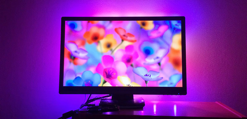
After figuring out the average color around the perimeter of the display, it’s just a simple matter of driving the LEDs. Tape those LEDs to the back of a TV, and there’s an Ambilight clone, made with an FPGA.
[DrX] has a few videos of his project in action. You can check those out below.


o m g
simply amazing
definitely a cool effect! especially for visualizations in the demos, great application. and the simplicity of the design and hdmi pass through is great. however, i’d think watching a movie like that would be extremely distracting?
I have an Arduino version.
No this is not, this is amazing !
Agreed this is near enough perfect to the Philips Ambilight TVs I see in shops or in the last hotel I stayed in Amsterdam. Watching movies in HD at night was simply amazing.
I’ve had an old laptop powering my TV for a while now and it has a DIY ambilight.
It may look like a gimmick but it seriously makes everything better. The first time you see an explosion and the entire wall lights up you will be sold. Probably one of the best bang for the cost/difficulty projects out there.
very cool affects but one must keep one’s mancave in total darkness in order to maximize the viewing experience
Or a white wall at the very least.
If this is a standard project for anyone beginning to tinker with FPGAs, then I am a long way behind. I haven’t even attempted to decode HDMI due the complexity of the signal. I’m still playing with VGA standards on CPLD.
Good project though.
What exactly is your approach? I was researching how to decode HDMI, I found a module that was supposed to just take TMDS signals in and spit out RGB.
If you are trying to decode TDMS from scratch, then I think it’s great that you are starting from the bottom up. But take a look from the top down, take an existing working implementation and take a look inside.
This is awesome and can probably be easily tweaked to make an HDMI-to-LED matrix adapter…
It essentially already is, just a ~300:1 downsample :)
I was going to do this years ago but kept putting it off, I kept doing the calculations for 1080p and it felt like I couldn’t do it without blowing an unreasonable amount of cash for just pretty lights.
I’m glad somebody took this project to the end. It is seriously impressive. I would be first in line to buy one that supported 1080p.
How was HDCP defeated?
It isn’t, but if you want to extend it to do so, look at the NeTV FPGA source code. HDCP is completely broken.
HDCP was avoided by not including a EDID/DCC ROM, so the HDMI source has no idea about the capabilities of the HDMI sink. Because of this it has to assume that it is ‘just’ a DVI-D monitor, and acts appropriately – which is to default to a low resolution and to not negotiate HDCP. This most likely won’t work with a BlueRay player of other source that is very DRMed.
Even without HDCP, a basic HDMI solution be ‘a bit’ more complex.
You would need to do would be to either not advertise HDMI without HDCP support (using a customEDID ROM), or make a clean source, for example some HDMI splitters produce a clean output on one of the HDMI outputs. You would have to watch out for the Video data preamble sequence, and then you can recover the original pixel data values as is done for HDMI.
However, you would also need to capture and decode the Video Data Infopacket (from one of the Data Islands in the HDMI stream’s blanking period) which uses the completely different coding system system. This is required so you don’t have to guess guess if the video stream is RGB444 (8 bits red, 8 bits green, 8 bits blue), YCC444 (8 bits Y, 8 bits Cb, 8 bits Cr) or YCC422 ( 12 bits Y, 12 bits CbCr, but the CbCr values are sent for every other pixel), With that known you would then need to convert the pixel data back into to the RGB colour space so you can use with the LEDs. This would require a configurable 422 -> 444 conversion, and then a configurable colour space conversion to go from studio level YCC (which uses values 16 to 239) to full range RGB, or from studio level RGB to full range RGB.
And that is just a basic implementation – a more complete HDMI solution could also support deep colour modes, where the data for pixels is spread over multiple data byte transfers. These have can have really funny bit alignments, so the HDMI source has to send pixel alignment information that informs the source what is about to be sent. So that is another Infopacket that needs decoding and acting on.
It rapidly turns from being a no-so-quick hack to being months of toil and not much fun…
his lights are still on while main screen is all black – I suspect it has something to do with 0-15 RGB levels being interpreted DVI style versus HDMI style
If you look at the source (‘averager.vhd’ in the git-hub repo linked on project page) there is a lookup table to convert the averaged value into the intensity for the LEDs – the Ambilight doesn’t really kick in until the average values us about 30%. and through the bottom end it has the LEDs on just a tiny smidgen.
I assume this is to prevent an annoying/jarring/distracting transition from completely off to just a tiny-tiny bit on.
Micah Scott (all around awesomo person, author of Fadecandy) talked about methods of extending dynamic range of smart leds on Elecia’s show (embedded.fm)
Micah’s project of Coastermelt is the closest I’ve seen for reverse engineering the functions can communicating with a of a blu-ray burner (conversely a DVD burner drive would work) to create a super high precision 2D lines, PCB cutter, graphite maker and anything else you can imagine.
Dang shame he only got to 75% complete and no one contributes to his github for it.
Micah Elizabeth Scott seems to present herself as a she.
Micah is a lass judging by the photos I’ve seen and her vibrator experiments.
Tho I suppose a male could still have done the vibrator projects.
@reboots – yeah, that was a typo. *shrug*, we don’t have a proper neutral pronoun to use. “them/they/it” doesn’t sound honorable either. Then again I grew up using the word “Dude” i.e. “Dude, that’s awesome”. Furthermore, Micah doesn’t seem flamboyant or an agenda pusher. Zero Fuchs given about identity. With that topic addressed/finalized and closed out.
So back to the original point I was making, the advancement, detail and effort put forth to documenting Micah’s projects is exceptional. Mad props and respect for COASTERMELT and encouragement to KEEP working on it and if anyone has the knowledge on how to address some of the more intricate details of BD custom functionality help Micah.
As I may have mentioned we could etch/burn PCB’s directly from a PDF if the diode focus is just right.
Current version is 720p max due to FPGA limitations.
I’ve always wanted to do a poor mans version of this with an old monitor attached to the back. Crank up the brightness and maybe use tinfoil or something to direct the light. Reverse the monitors image. Might need to pull the TV out as well. Crude but free.