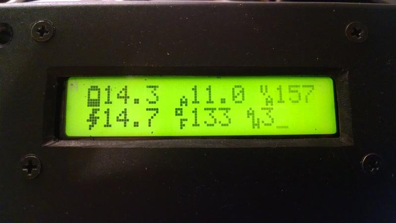
This is a story mostly of decoding data, but there is a happy ending that includes turning that decoding work into an open source receiver. Xantrex solar charge controllers monitor a lot of data about what is happening with your solar panels, and they stream it over RJ25 but you need their add-on hardware to receive it. [Eric Herbers] figured if the data is being transmitted, a resourceful hackers should be able to decode it. And he did just that with a little help from his friends in the Hackaday community.
We asked on Twitter what people were working on and [Eric] posted his scope screenshot. The conversation that followed helped point him in the right direction and others knowing about the project surely drove him to finish it. The decoding isn’t perfect, but achieve enough to decode and display voltage, amperage, and temperature. [Eric] built the display unit using an Arduino Pro Mini and a character LCD housed in you most common of black project boxes.


Step one is researching common protocols and data interfaces instead of just jumping in and guessing. Today hackers have an endless instant resource. Back in the 80’s when I was hacking stuff like this you had to social engineer information out of the manufacturer and it took weeks to get anything useful.
Modbus is a protocol that when used over rs485 will make you vow to find and beat with a sack of doorknobs the engineers responsible for it.
Blowing a fuse. tim?
Too bad newer xantrex devices dont use modbus, they use Xanbus protocol. if it was as easy as modbus there is already the published spec on the web explaining that protocol.
Modbus spec lacks specific uses for specific ‘registers’, thereby making any given modbus implementation very likely to be different than any other modbus implementation.
Eric here! A little clarification in that it’s not wireless, everything is transmitted over a rj25 cord.
By all means, this doesn’t appear to conform to any known standard unless you know of one that starts a frame of data by bringing both communication lines high.
Thanks for the clarification Eric. I’ve updated the post.
wait in the tweet is he saying he has never seen differential signaling before? O.o
There’s a first time for everyone! I never claimed to be an expert at anything. Seeing as how my education is mechanical engineering and my background is providing tech support for farm equipment, is it that surprising I’m relatively green about serial communication? :)
That said, the tweet as more about I had never seen serial communication in which it was only 8 bits per packet. I was expecting to see some sort of preamble or start/stop bits. Instead it was just 8 bits a piece, each seemingly adding up to reasonable values. It wasn’t until later that I finally caught a glimpse of one packet in which both comm lines were high and the gears started turning.
ohhh okay i get it … it does sound kinda like RS-485
it has a high start bit and a high stop bit but both interestingly enough can be ignored as long as the first bit is high and the last bit is high to simplify the protocol but its not exactly good practice
Yeah, but neither is true in this case. All 8 bits are used to form a number from 0-255.
does it float when not sending data?
Data is sent continuously with a short pause between packets. Both comm pull low during this pause.