A lot of young athletes who get concussions each year go undiagnosed, leading to brain injury. [Hunter Scott] is working on a device called Impact to help detect these events early. According to this article which discusses the issue of concussion recognition and evaluation, “Early identification on the sports sideline of suspected concussion is critical because, in most cases, athletes who are immediately removed from contact or collision sports after suffering a concussion or other traumatic brain injury will recover without incident fairly quickly. If an athlete is allowed to keep playing, however, their recovery is likely to take longer, and they are at increased risk of long-term problems”
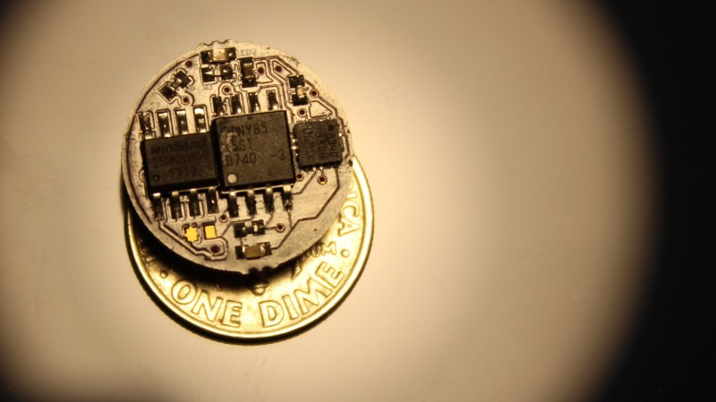
The device is a dime sized disk, which has an ATTiny85 microcontroller, memory to hold data, an accelerometer and a LED which gets activated when the preset impact threshold is breached, all driven by a coin cell. This small size allows it to be easily embedded in sports equipment such as helmets. At the end of a game, if the LED is blinking, the player is then screened for a concussion. For additional analysis, data stored on the on-board memory can be downloaded. This can be done by a pogo-pin based docking station, which is what [Hunter Scott] is still working on.
He’s having a functional problem that needs fixing. The ATTiny85 cannot be programmed with the accelerometer populated. He first needs to populate the ATTiny85, program it, and then populate the accelerometer. He’s working in fixing that, but if you have any suggestions, chime in on the comments below. We’d like to add that [Hunter] is a prolific hacker. His project, the Ultra-wideband radio module was a Hackaday Prize semi-finalist last year.


I am curious why the impedance change is such a setback for programming the device. The only thing I can imagine is it causes the data lines to draw too much current for the programmer to supply. If this is the case, a few unity-gain buffers (using op-amps or a using “flipped voltage follower” for brownie points) in series with the data lines will likely fix the problem.
My guess is that the pull up or pull down resistors on the programming lines are creating a voltage divider with the pull up or pull down resistors internal or external to the accel and scaling his logic high and low voltages. Oscilloscope on the data lines should be able to confirm. Solution in that case would be to add an external pull up or pull down resistor that modifies the voltage divider in favor of the programmer, such that when it is connected the resulting scaling factor doesn’t cause the logic high and low voltages to fall below or rise above their specified thresholds. I could be more specific but there is not enough information provided to accurately diagnose the problem.
I suggest adding solder jumpers between the microcontroller and accelerometer. Populate both parts, program the microcontroller, and finally solder the jumpers closed. The only problem is that they could be difficult to fit on that board. Perhaps only one (for the accelerometer’s power or ground line) would be enough.
hi!
it looks like the attiny85 communicates with everything else through SPI?
actually you only need a solder bridge on the MISO line – everything else can be always-connected, because only the MISO line is an attiny85 input.
so you want the programmer and attiny85 directly connected, and a solder bridge connecting the MISO to the flash and accelerometer.
or you can try using a high-ish value resistor (>47kOhm) instead of a solder bridge!
Some similar projects here http://www.element14.com/community/community/design-challenges/sudden-impact?ICID=DesignCH-top3Challenges
There is also this one, https://www.triaxtec.com/sim-g/
What about programming the bare micros before they are installed?
I’ve had “unreliable programming of in-circuit AVR processors” problems. A programming attempt would brick the AVR. When this happens in circuit, you can throw away the whole board. So we now put the blank AVRs in a zif socket, program them, and then put them on the boards.
> When this happens in circuit, you can throw away the whole board.
That’s fairly wasteful.. why can’t you depopulate the junked ones and solder in a replacement?
I doubt it’s an impedance issue. Assuming SPI mode. More likely your Chip Select is floating, and the accelerometer is spiting out data onto your SPI programming lines. Add a pull-up to ensure chip isn’t active when the ATTiny is in it’s reset state.
Ah, that makes sense. If the design depends on the pull-up inside the ATtiny the lines will float during programming. Nice troubleshooting!
Looking at the schematics http://imgur.com/a1YKdmC , he seem to connect both CS pins to single IO pin, using the fact the chips do have opposite CS levels – so toggling the IO actually toggles which slave is selected. And there is ALWAYS one slave selected.
It seems super simple, but as one slave is always selected, it can and will interfere with programming data. I’m afraid there is no simple remedy for this, just to redesign it, or include some jumpers on board.
Or you put a high enough value series resistor for the pin that drives it. The programming hardware is hooked up on the other side of the series resistor so it can override the signal level.
Since the sensor is already a QFN, there is not reason why he can’t use a AVR part with more I/O in another QFN package. With more I/O, you wouldn’t need to do mickey mouse hacks.
Very nice, much wow, Doge like!
One thing that I saw a long while ago with programming the 328p was that if you had any kind of diode on the spi lines while trying to program in system would cause too much of a voltage drop and the spi bus would read data incorrectly or not at all…try sticking an n-channel enhancement MOSFET for isolation in the system so when it goes to program it you can isolate the accel. Using the reset pin on the avr connected to the gate….hope that makes sense….it’s been awhile since I had this issues.
Also I think this is a great project, but what are you using as the standard of impact force that would cause a concussion. I would also think that changes from person to person.
The idea is if you exceed a number you should be tested, not that you definitely have a concussion. If you search on the tubez, it looks like 100G is about the threshold for a possible concussion.
Exactly. Potentially de-rate slightly for component tolerances and safety margin. (Test people that fall just a little below the line)
How exactly would you test someone besides possibly giving them a concussion? Seems counterproductive to the object of design.
MRI
Can’t help but wonder about temper proof commercial products that are designed for monitoring g forces for packages during shipping. Stick them to the helmet etc. and you are set.
http://www.shockwatch.com/monitoring-devices/impact-sensor/impact-indicators/
Those are the ones the Mythbusters use. I love how frugal they are, they cost pennies a piece.
The only problem with using Shockwatches, is they are single use. one hit and they are done. This solution will be reusable and can actually give you usable data to help with diagnosis as well.
A ShockWatch is also reusable, they won’t trigger unless the G forces involved are enough to cause a concussion. The ShockWatch has its limitations, but it’s a lot cheaper than the sim-g. It’s would be nice if this project had real time monitoring like the sim-g. Right now Triax has a monopoly on the market, and it would benefit everyone if they had some competition.
no it’s not, once it trips you can’t reset it.
Reusable if it hasn’t been triggered during the previous shipment….
How many Shockwatches does little Jimmy need to trip before his parents wise up and find him a new hobby?
The single use nature is not necessarily a drawback. The number of stickers shows how many times that helmet has done its job. You want to replace the helmet too after a few hits.
I would at least use the sticker as a temper proof backup system just in case the electronics failed or that it was reset because the person using it don’t want to be benched.
The programming issue is actually pretty straight-forward to resolve and in a way that will still let the item be assembled then programmed after and not need any solder jumpers as a few others have suggested. A 10-100K resistor isolating the “DO” of the two SPI devices from the MISO net, but make sure the MISO programming pin still connects straight to the AVR. The AVR programmer should have no trouble overriding this signal now.
In concept this is very similar(exactly the same) to a hack posted a while back about using serial lines for more than two devices, but one will ‘override’ the other by way of a lower value resistor. I’ve been using this basic theory for quite a few things lately. The reason I listed a range of values for the resistance is that on larger boards capacitance can cause high speed signals to form miniature RC circuits, so just peek at the lines with a scope probe and make sure the edges look right if using a high value resistor.
I can’t find via search the post in question but if anyone knows where it is feel free to link it to better explain the theory of overriding signals. In practice it’s often a bad idea to actually short inputs to outputs without a resistor in-line so long as board space isn’t at a premium like it is in this tiny board.
Maybe a silly answer but, why don’t you just use another chip?
Something like the stm8s003f3u6. It had a nice QFN20 package of 3x3mm so easy to fit in to your project and SWIM in-circuit programming en debugging. And for the cost of 0.30 á pcs its much cheaper then the Attiny85.
Or if you really want it small, but a bit more expensive you can use the Freescale kinetis KL03
http://www.aliexpress.com/item/STM8S003F3U6-QFN20-genuine-original-spot-false-a-compensate-eleven-starting-a-large-quantity-of-excellent-price/32302144113.html