It only takes one mistake to realize electrolytic capacitors have a polarity, but if you’re working with old tube gear, tube amps, or any old equipment with those old orange dip, brown dip, or green dip foil capacitors you also have to watch your polarity. These old caps were constructed with a foil shielding, and there’s always one side of these caps that should always be connected to the chassis ground. If you don’t, you’re going to get interference – not something you want in an amplifier circuit.
Old caps that have long since given up the ghost usually have a black band designating whatever side of the cap the ‘foil ground’ is. This is the side that should be connected to ground. If you look at modern foil caps, you might also see a black band on one side of the cap, which should – if we lived in a just world – also designate the foil ground. This is not always the case.
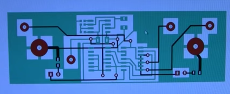
To properly test foil caps and determine which side should be closer to ground, you can construct a small tester box that’s more or less an h-bridge with a single switch and a pair of alligator clips in the middle. Connect the cap to the clips, put the output of the circuit in your scope, and flick the switch: the direction that has the least amount of interference is the denotes the foil ground of the cap. Replace those old caps in your vintage equipment with a new, correctly oriented cap, and you’re well on your way to having a great sounding amplifier.
Video below.


Its not foil “ground” where marked (not all foil CSPs are soarked) it marks the lead connected to the “outer” foil.
Usually, you want that grounded, or at least connected to the lowest impedance part of the cct.
If this is true, there is no telling how many of those orange drops I’ve installed backwards. Hopefully a few more comments left will help me figure out if Dave B is right or I have to go and undo all of these in the tube radios I’ve cobbled on.
You will only have to work on those radios that display the symptoms mentioned that could be caused by caps installed “wrong” in the video
Interference at audio frequencies? Could this be true? Or is it a polarization effect due to the initial testing voltage?
Not all of these old cap were polar. Some of them had positive marked instead of negative as there was no standard in the early days.
If in doubt – be adventurous put a cap in, if it explodes put the next one in the opposite way lol.
While there is a lot of fun to be had in blowing capacitors up, foil caps won’t blow if reversed.
I had some fun with that too. I had part of an electrolytic stuck in my garage wall for several years!
Nice!
I found out many years ago that big caps make little caps go boom. :D
(I also found out that electrolytic caps smell really, really bad when they go off)
Remember: Once you let the magic smoke out you can’t get it back in. That’s why it’s magic.
Back when it was thought electric current flowed from positive to negative, there was the left hand current rule. Curl your fingers around a wire with your thumb pointing in the direction of the current and your fingers indicated the direction of the magnetic field. (This is not Fleming’s left or right hand rule. Those involve pointing thumb, index and middle finger in three different directions and wires moving through magnetic fields.)
They got that part right but after discovering that electric current actually flowed from negative to positive the fix was easy. Flip it to the right hand current rule. Magnetic field stayed the same but now the right thumb points the direction of current flow.
That misunderstanding is why vehicles used a positive ground electrical system until around 1955. Since electrons flow easier across a spark gap (as in the spark plugs) from a hotter to a cooler electrode and the side electrode extends farther into the combustion chamber, the people who designed ignition systems thought they had the electrons flowing from the battery to the chassis, to the engine, through the spark plug shells and side electrodes, across the gap then up the ignition wires to the distributor.
After it was figured out they’d got it backwards, vehicle electrics were quickly switched to negative ground. Many people still think of plug wires carrying electricity *to* the plugs when they’re actually carrying it *from* them.
What is amazing is that vacuum tubes and so much other direct current electrical stuff was designed and worked despite the common knowledge of electron flow that was backwards for decades. Makes me wonder if any vacuum tube engineers ever thought to themselves something like “How the bleep did we make these things work when the electrons were going the opposite way we thought they were?” after they got the news that what they knew about current flow was wrong?
Motors use magnetic fields and since they had that right, it didn’t matter that the knowledge of current flow was wrong, it worked anyway, and for alternating current it didn’t matter at all.
In semiconductors there’s what is called positive hole flow, the “holes” in the atoms’ ‘electron shells’ that the electrons jump from one to the other like marbles on one of those game boards. The holes don’t actually move and the phenomenon only exists within semiconductor materials.
I used to have some 1970’s electrical and semiconductor course books that had a section explaining the original error, the left hand current rule and the right hand current rule that superseded the left hand one. It also had a section on vacuum tubes, though largely supplanted by transistors by the mid 1970’s could still be found in many early 1970’s and older TV and radios.
As I read it was until when vacuum tubes came onto the scene that is was realized Ben Franklin e. al. got it wrong when they had a 50/50 chance. Because electrons flowing from to positive to negative didn’t plain what they where seeing with vacuum tubes. As you mention solid state came along, requiring another reevaluation. Now electrical current is described as the flow of charge carriers, both electrons and holes. The hand rule have no application in determine if electrons flow from negative to positive. Those hand rules are only applicable when there is movement between a magnetic field in a conductor or the nature of the magnetic field surrounding a conductor with current flowing through it as far as I recall. There are many theories as to what best for motor vrhicle negative or positive ground Some say the spark is some how hootter, there is less metal corrosion, and as safety factor with a negative ground. All this is moot point because this video isn’t about polarity sensitive capacitors
Electron flow has been known for a long time. We just continued to use the convention of current flowing from + to – because it makes no difference in most cases.
I’m confused by your comment:
“Many people still think of plug wires carrying electricity *to* the plugs when they’re actually carrying it *from* them.”
Will you clarify it a bit? I’m under the impression that electrical energy is conveyed *from* the source (e.g. induction coil in modern cars) *to* the spark plugs where it is used to create a spark. Is that understanding incorrect?
A bit more pondering and my confusion becomes clear: the wire going to the spark plug is just a single wire, with the other half of the circuit being made through the body of the spark plug and the engine. So your comment makes sense, it was just my lack of knowledge about cars.
On the other hand, that implies the induction coil is actually “pulling” electrons through the spark plug. I’ve never thought of it that way, but that’s really cool.
The coil sucks the spark out of the spark plug.
Vehicle electrics changed from positive earth to negative due to galvanic corrotion ( to the best of my knowlege) runnibg negative earth reduced body/chassis corrotion.
Cars also run wasted spark ignition where the spark comes from either end of the high temsion coil, so one plug has electrons flow from tip to shell and the other vice-versa. This is very obvious when you inspect the plugs on a poorely serviced wasted spark vehicle, some plugs are eroded on the electrode and some on the shell. Long and short it doesnt matter :)
You should actually watch the video sometime.
I wonder if his initial testing with the scope could be duplicated by plugging the coax into an audio amp and comparing the loudness of the 60hz hum with with polarity.
The first time I learned that caps were polarized for a reason, I was using a big old cap that didn’t have a safety vent.
So do modern-day metal-film capacitors suffer from this also? One layer must be exposed more than the other, interesting!
Wait a minute… At 6:05 he puts the capacitor at the beginning stage of the circuit to show that it “always” connect the foil to the previous stage, but where he connected it was actually ground and therefore reversed. So, which rule is followed?
What I want to know is how these are correctly oriented in mass-produced products. If the caps aren’t marked, it seems like a 50-50 chance of going in the “correct” way. I have a hard time thinking that they check the orientation of every damn foil cap they put in.
yes, also since these are typically rated for higher voltages I’d imagine having the live side on the outside foil makes it marginally more dangerous, if you poked though it you’d hit a live terminal before a grounded one.
Though that’s mostly for a DC application, I know the main use of these is forming capacitive droppers in cheapie AC circuits.
Also this was posted just recently, I thought it interesting to see modern day film capacitors failing by what seems to be a chemical issue.
https://www.youtube.com/watch?v=qGc9-ToEiIQ
Remember the electrolytic mass failures.. version 2.0 coming up? Fool me once with crappy capacitors shame on you, feel me twice, shame on me for purchasing garbage.
Probably should be use Class X caps + bleeder + fuse for capacitive droppers.
Hello Mr Carson,s I like to ask you if you have the PCB available as I like to build one..
Many thanks
Regards joe
9H1GT
Yes, right. Good luck with your request. He is in this strictly for money. On youtube he rarely responding unless you are an internet personality (right, there is such thing now). He knows things, I do not know what is his trade, but when comes to explain, is like one of those Engineer that I am used to, knows a lot but on the explaining…well he should do something else. To the main topic, there are a lot of holes in his procedure, even he knows (and I am sure he knows very well what he does) or he just trying to get people on his Patreon page. I try with a modern oscilloscope and it did not work, tested several capacitors, old and new, nothing, obviously I did something wrong. I watch the video several times and I made all kind of notes and couple of my friends did the same thing and nothing. The entire information is not disclosed unfortunately, I think, but I might be wrong. And yes, everything is there on Patreon(with a small fee you can join de “club”) for this project. I will unsubscribe from his channel since is little deceiving. Al things said I stick with an old book, the info is priceless and if you get the right one, you might even learn something good. Mr C, please have your procedure rethink and even use a modern oscilloscope, most of us we step on 21st century, from measurement equipment point of view, why would I invest in an old oscilloscope when I can get a modern one. I hope I did not insulted anyone, It is jus a constructive criticism.
I know why your “modern scope” won’t work. Low is not likely connected to earth. You need to add an extra binding post to the chassis to attach the outer BNC to Earth ground, The ground prong of your AC outlet.
It should also be obvious, that you have to “hold” the capacitor.
I’m surprised you can’t get away using a 4PDT switch. You do have to shield the wires going to the alligator clips.
In my professional life, I dealt with measuring sub picoamps in high Z circuits.