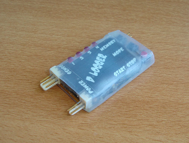
[Rui] enjoys his remote-controlled helicopter hobby and he was looking for a way to better track the temperature of the helicopter’s engine. According to [Rui], engine temperature can affect the performance of the craft, as well as the longevity and durability of the engine. He ended up building his own temperature logger from scratch.
The data logger runs from a PIC 16F88 microcontroller mounted to a circuit board. The PIC reads temperature data from a LM35 temperature sensor. This device can detect temperatures up to 140 degrees Celsius. The temperature sensor is mounted to the engine using Arctic Alumina Silver paste. The paste acts as a glue, holding the sensor in place. The circuit also contains a Microchip 24LC512 EEPROM separated into four blocks. This allows [Rui] to easily make four separate data recordings. His data logger can record up to 15 minutes of data per memory block at two samples per second.
Three buttons on the circuit allow for control over the memory. One button selects which of the four memory banks are being accessed. A second button changes modes between reading, writing, and erasing. The third button actually starts or stops the reading or writing action. The board contains an RS232 port to read the data onto a computer. The circuit is powered via two AA batteries. Combined, these batteries don’t put out the full 5V required for the circuit. [Rui] included a DC-DC converter in order to boost the voltage up high enough.


I like the portable reader. I’m wondering how long the logger would last on a few coin cells (to keep the weight down on a smaller model)
Does anyone know if there is a link to the spreadsheet? I’d like to see the approach used to read the data.
Kind of curious on the insistence of using 5V for battery operated devices when there are plenty of parts in the last 15 years just happy with 2.7V or lower. Parts specs have included 2.7V (instead of just 3.3V +/- 5%) as their wider range are intended for battery operations. The 2AA cells used could have power the right chips directly without requiring the extra 5V boost circuit.
I can understand using boost circuit for a single AA to save weight. There should be plenty of battery capacity in today’s AA cells.
You could use the batteriser to improve the performance of a single AA even more ;)
http://www.batteriser.com/
Oh, you…
Or some dude from India can tell you how to run it perpetually.
Or someone with spiritual powers to ask the fire elementals for the temperature directly. :P
I think I would have gone with a 3.3v Pro Trinket, a thermocouple amp, and a K-type thermocouple. This would have cut down on weight, allowed it to work without a boost converter and all of the RF noise that goes with it, and use a lighter and more robust sensor.
That being said, I think this is a very well done project.
At such “low” temperatures, why a fussy thermocouple instead of a RTD?
Why even external battery pack? All my stuff have 5-6.2 v packs for the radio equipment
I was contemplating this one. Perhaps this option was chosen for portability or maybe simply the noise factor and sudden power draw might cause unstable operation. Although a Zenna/resistor/largish capasitor combination (or reasonable regulator) might well do the trick.
We used to live dangerously and use 7.2V NiCd pack that powers the motor with 2 diodes drops for the radio/servo.
Nice idea, but the EEPROM makes it a bit unhandy. It could be made even more awesome by writing to micro-sd! Also, I’d use an Arduino ;-)
micro-sd needs quite a bit more code to be usable. For one, you’ll need at least a MSDOS file system on the PIC so that when you put the SD into a PC it would read it. If it is RAW without format, why bother?
That file system alone would have taken more than the memory on the PIC.
Why not use the radio power? This is the way that I did it 20 Yrs ago for a datalogger that we used in Giant Scale Racing (AeroSport EDL-II & EDL-IV). I also used type K thermocouples for EGT and CHT. I also had tach via a hall sensor (and True Airspeed on the EDL-IV).
What is old is new again ;-)
Thermal paste is no more a glue than axle grease is. His sensor will work itself loose eventually, which could lead to problems if the wires get tangled in something.
I think he meant something like this: http://www.arcticsilver.com/ta.htm
Looking closer at his photos that is what he used. Both the write-up and the article say ‘paste’ though. Which isn’t the same as thermal adhesive.
Tekkleneet: Probably stuck with 5V rather than 3.3V because the LM35 requires 5V. (I learned that the hard way. :-p ) The MCP9700 is a pin-equivalent 3.3V part, though.
Leithoa: Arctic Alumina is actually a 2-part thermal epoxy, not a thermal paste. A good choice for this application: I’ve been using it for physics labs for awhile with zero failure rate.
Rick: Nice work!
I would used a LM73 with 2 wire interface (and yes it works up to 150C and 2.7V). No need to use analog sensors.
Arctic Silver also sell an alumina based paste that does not cure or have significant adhesive properties. As pointed out in my other response, the write-up says paste, which is different from adhesive.