On the path to exploring complex logic, let’s discuss the electrical properties that digital logic signals are comprised of. While there are many types of digital signals, here we are talking about the more common voltage based single-ended signals and not the dual-conductor based differential signals.
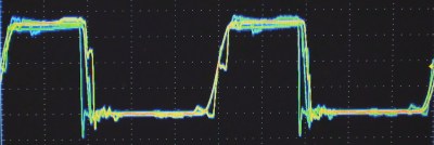
I think of most logic as being in one of two major divisions as far as the technology used for today’s logic: Bipolar and CMOS. Bipolar is characterized by use of (non-insulated gate) transistors and most often associated with Transistor Transistor Logic (TTL) based logic levels. As CMOS technology came of age and got faster and became able to drive higher currents it began to augment or offer an alternative to bipolar logic families. This is especially true as power supply voltages dropped and the need for low power increased. We will talk more about CMOS in the next installment.
TTL was a result of a natural progression from the earlier Resistor Transistor Logic (RTL) and Diode Transistor Logic (DTL) technologies and the standards used by early TTL became the standard for a multitude of logic families to follow.
TTL Signal Voltage
When connecting two logic gates together there are essentially four voltages of interest: the high and low voltage that the gate’s output will produce, and the high and low voltage that the gate’s input is expecting.
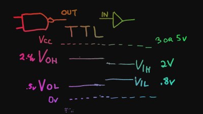
| TTL Output signal voltage specification: | |
| Voltage Output High VOH | 2.4V |
| Voltage Output Low VOL | .4-.5V |
| TTL Input signal voltage specification: | |
| Voltage Input High VIH | 2V |
| Voltage Input Low VIL | .8V |
In short the output gate generates a slightly larger signal than required by the input gate; the difference between the output and input voltages allows for some loss of signal and/or the addition of some noise into the equation. This difference is often referred to as the noise margin.
TTL Voltage Compatibility
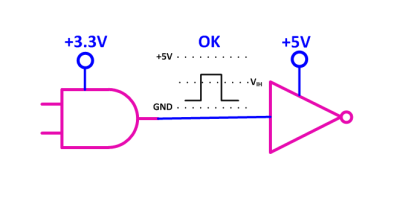
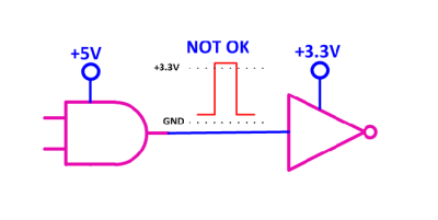
The TTL signal levels are usually the same, or very close for both “standard” 5 volt TTL and for low voltage 3.3 volt TTL, often referred to as LVTTL. While this would sound like they should then be able to connect together safely there is however a specification for most TTL/Bipolar logic families that states that the input signal cannot exceed the power supply by more than a few tenths of volts. There is a possibility that a 5 volt gate may generate more than 3.3 volts on its output, hence the problem.
There are logic families such as 74AHCT that are tolerant of higher voltages than their power supply on their inputs, however this is a CMOS family and will be discussed in the next post.
Schottky Logic
Before I do a quick summary of the Bipolar/TTL families let me first explain what a “Schottky” family logic device is and where it gets its speed improvement from.
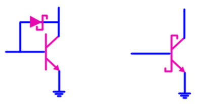
A transistor when used as a switch can go into a state known as saturation. Part of the definition of “transistor saturation” includes the state when both Base-Emitter and Base-Collector junctions are forward biased, however the property of interest here is that it is also slow to turn off as there is an excess of charge built up that has to be drained off first before the device starts to respond. A Schottky diode across the base-collector junction effectively holds the transistor right on the edge of being turned “on” and keeps excessive charge from building up. A transistor paired with a Schottky diode in a gate is often redrawn as shown above on the right.
TTL Logic Families
| 74 | Original TTL – Some parts still around. |
| 74LS | Low Power Schottky – Good compromise speed vs power/noise and inexpensive. |
| 74S | Schottky – The sledge hammer of the early TTL, speedy but a heavy lift. |
| 74AS | Advanced Schottky – When you really to go really fast. |
| 74ALS | Advanced Low Power Schottky – Fast and low power, however not without noise considerations due to the speed in which the signal changes (slew rate). |
| 74F | Fairchild Advanced Schottky TTL – Fast and low power, a little less noisy than ALS in my experience. |
| 74L | Low Power – Not widely used. |
| 74H | High Speed – An early compromise for more speed, not widely used. |
Here you can see the bipolar TTL based families. Some of the families above are also able to sink and source a lot of current which we will also compare to their CMOS counterparts in the future.
Glitch Quiz
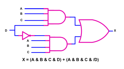
Lastly if you remember the last post which covered Basic Logic, I asked about a risk of a glitch in the circuit shown below on the left. The glitch would arise when “D” changes state because in theory there is a time when one equation, known as a term, has stopped being true before the other term has become true. In fact the D signal itself is not needed as the two sets of terms were otherwise identical
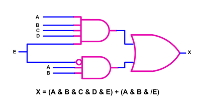
Looking at the circuit on the right; have we gotten rid of the possibility of the glitch since the terms are no longer otherwise equal?






Totally forgot about that book… thanks for remembering…
just ordered my own copy for 66cents+shipping :)
Debugging that dead freq-counter would have been faster with all that datasheets readily available…
73
In the old days we would have to defend books through the old hardware ritual of running at each other and crashing heads or the soldering iron sword fight (A common way to cheat to was to pretend to get winded and then throw flux in their eyes). My book has a big “H” on it for identification purposes for that reason.
I add that book too. But who use TTL nowadays. I’haven’t used them for so many years…
correction: “I had that book too.”
TTL is really only of historical values these days. CMOS is the most popular cost effective technology. It doesn’t make sense to talk about things that are going obsolete.
If I were to teach a course, I would talk about CMOS, HSTL, LVDS/PECL/CML. FPGA and how they implement the I/O standards internally is a really good topic right there.
I’m getting there, the TTL standard for voltage highs and lows is still with us and when I skip too far ahead I end up backtracking at some point. This was also a starting point for the discussion for 3/5v compatibility and also real life waveforms.
The whole “maker” thing has too many obsoleted technology. Time to start thing new. No more 7805, 555, 74XX, LM324 parts please. 3.3V is also on the way out, but it would stay around a bit. Ditch the 5V now. There are much better parts out there 40+ years later guys.
What’s wrong with the LM324? Do you know of a better quad op-amp, that’s available just about everywhere, and often for $0.15 in single quantity?
Ya, love the 324.
Not a issue when it is used for the right application for those who can read datasheets and actually design stuff from scratch. “Makers” with their copy/paste without thinking herd mentality do not fall into that group.
However with the limits in GBW, slew rates, the weak sink, lack of RR I/O etc., it is not a general purpose part for *every* darn projects out there. May be when it was designed back in its days… Certainly does not belong into a scope input stage. I have seen it in open source projects because the persons don’t know better. it is also a horrible part if you want to use it for 3.3V and below.
Ok [Tekkieneet], I understand now – it’s included on that list of parts because it’s not as useful below 5V. The other specs you brought up are a good list of the basic specs one should consider when using op-amps.
Most of my projects are interface, automation, LED lighting, motors and servos, etc. Usually with a 5V or 12V rail around in addition to the 3.3V digital rail, and no signals over 100khz. The LM324 is still plenty useful for stuff of that nature.
I have actually found myself doing little circuit kits that specifically use through-hole and “easier” voltages so that hobbyists can do the assembly and troubleshooting. (I assume not everyone has a microscope and precision power sources )Also 30 year old AVR’s don’t appear to be going away any time soon.
I’m confused and perhaps a Luddite. If 5V and 3.3V are going out of fashion what on earth are we going to use? ±15V? Blimey I hope not.
I’ve got loads of 5V kit that works great. USB is 5V, it just makes life easy.
@eanao: no, the move will be to lower voltages, such as 1.8V
When a product from the 70’s is still manufactured it is because sales volume justify it. So the 555 is justified, but moderns 555 are CMOS.
No, it’s not particularly relevant to IC-to-IC interconnects anymore. But what if you need a particular circuit function, and would rather combine a handful of discretes than use an IC, or you have no choice because no IC is available with exactly the characteristics you need?
Then you’d better know how to put together transistors into useful combinations, and TTL is still a great example of that. CMOS, HSTL, LVDS/PECL/CML are increasingly less useful for discrete circuit design, unless you’re one of the few in the biz of designing ICs.
For people that figures out that they need to create a specific function out of discrete, they won’t be the “maker” copy/paste Arduino generation i.e. they can think for themselves and they should do just fine. Bare in mind that thew performance of building gates out of discrete parts aren’t that great. Except for emergency/end of the world situations, there aren’t too many reasons to do so. It is easy enough to make logic function using FPGA/CPLD these days.
try mounting that fpga on a breadboard. i have a few fpga boards but my bin of 7400 parts gets used more than the fpgas do.
True, I wouldn’t actually use discrete-built gates in a most real-world projects. But at the discrete level, they’re analog. Analog electronics did NOT come easy to me, coming from a pure digital (programming) background. Understanding how a component works alone just wasn’t enough. I studied lots of circuits, including TTL output stages, until I could more intuitively understand them. Designed dozens of complex circuits in SPICE, most of which were just self-imposed learning experiences, and will never see the real world. At least now when I need to design an analog circuit for real-world use, it’s not a completely intimidating. But it’s still an ongoing process. It was only a few years ago that I encountered a diamond buffer for the first time, and wondered why such an elemental circuit isn’t covered in any Class B amp tutorial. And while I knew about using a regular diode to keep a bipolar base from going into extreme saturation, I didn’t know a Schottky would even allow the base voltage to rise high enough to turn it on, until Bil mentioned it.
I have done hacking a long time, so I have made a lot of discrete stuff on my own before the web existed. These days, I don’t do mickney mouse logic anymore.
From my experience, not a whole lot will be missed on the TTL and older parts unless you are a museum curiator. They are important for a 2nd year level circuit analysis course for real engineers that want/need to learn the analysis skills. So when someone throws a dusty schematic that look unfamiliar to you, you might know what blocks are there or at least not intimidated by it.
Sure you can see how things are put together, BUT some of the circuit techniques are optimized for making chips where you throw transistors in as they use less chip areas than a passive part. They also get to match/control their transistors characteristics. So not sure if you really want to replicate that design decision with discrete.
Basic stuff like driving MOSFET, transistors, level translation without using silly optoisolators, cascode, current source, switch mode supplies, layout techniques, understanding current loops, signal integrity etc are more useful from a practical sense. They are all done very poorly these days by the average “makers” that copy/paste badly designed stuff from each other or their webcelebs.
I don’t do breadboards. When we do 100+ pages of design for large projects, we don’t do bread boards.
I think I have outgrown that obsession with DIP packages, breadboard except for very low performance, very low complexity circuits that I don’t intend to keep around. That must have been like a few lifetimes ago for youngsters. Even my simple hobby stuff starts with more chips than fingers on one hand these days and they are all SMT.
Most people here are hobbyists and not really interested with projects having a 100 pages of documentation. SMT takes way too long to prototype anything. By the time you layout a board, order a few PCBs, the build it up a month has gone by. Most of the time I’m not interested in waiting that long to try out a new design.
Most of your posts today are “I don’t do this in my day to day work so no one should”. If you don’t care about this article, you do not need to let everyone know how it is irrelevant to you. It is relevant to lots of other people. Some people like learning the basics before moving to the advanced stuff.
I still use TTL ICs all the time (by TTL I’m essentially talking about 7400 series ICs (but the variety of types of TTL in there vary wildly)). The 595 (serial to parallel shift register) comes in handy in quite a number of my small projects when I need a to add a few more IO pins to a small microcontroller. The 3.3V levels out of most microcontrollers have no problem interfacing to 7400 ICs (at least in the one direction…. it better be 5V tolerant in the other direction unless you like letting the magic smoke out). Sure, I probably wouldn’t design modern consumer electronics with ’em but TTL is still very commonly used. Used a SN74LS07 on a project just last week because it’s open-collector output was perfect for getting the 28V signal levels out of an TeensyLC. Sure I could have chosen any one of a bucket of options to get that 28V signal level, but why mess with something that’s cheap, been around forever, does the job, and most importantly, you’d have lying around.
Mainly engineers use 7400 series ICs because there are a crap-load in pretty much any well-stocked and electronics lab that’s been around long enough. And, because most of my projects are one-offs, I design mainly off the parts I have on hand. May not be the most efficient or cheapest route, sometimes, but my requirements are to churn out hardware hacks as fast as possible.
And Bil, I hate to be the douche that points this out, but your Schottky diode symbol looks a hell of a lot more like a zener or TVS diode than any Schottky symbol I’ve ever seen.
I use the ‘595 as well, but not the TTL version but CMOS, and never the 5V version (unless in rare cases I need to interface with 5V-only stuff).
Wow brain infarction, thanks. I drew it looking right at a chip schematic and kept wondering what was wrong, usually I misspell schottky. Never would have made this mistake in my youth,. >:)
(I would have made whole different mistakes)
The image has been updated.
Off the top of my head I can think of two things old 74xx logic does better than CMOS. First it’s loads more ESD tolerant. Second, it only uses NPN transistors so it doesn’t have the parasitic SCR that CMOS has. So no “latch up.” Makes it much more radiation and abuse tolerant.
Shouldn’t you better stop the abuse from reaching your logic chips in the first place ?
In a perfect world yes. Often there are layers of protection in an environment where there is true ESD with the more exposed circuits getting more protection. Other times things like driving a switch panel or some inductance has accumulated you may get into an area where the chips protection is adequate and the cost and parts count are important. Sometimes protecting lots of high speed lines can take up lots of board space and be expensive and double part count, while inducing other problems at the same time.
If you are interfacing to the real world in a product, you would have put in parts for EMC, right? Not seeing that too much parts as a good excuse for not protecting thing properly.
Low pass filters helps with some what with ESD as they stop fast edges and that’s what ESD has. Better grounding, better containments, shieldings helps.
I plan on talking about where the latch up comes from and how protection got better when I talk about CMOS, and how removing some of the protection allows us to translate higher voltages on inputs.
This is a great series, really looking forward to learning more about fpgas, having never done electronics at college or uni. A shame there was quite a while between this article and the last, I thought it might have been scrapped.
I’m only a tinkerer with simple circuits, basic micro controllers and raspberry pis, helped somewhat by being a computer science graduate. I got posted on HaD for a tiny PIC driven micro led matrix, some time ago, highlight of my life! ;-)
Can somebody please explain what Bill means by bi-polar electronics? I’ve heard it many times in my electronics hobby but never really spent the time looking into it. If I did I probably forgot! I know it’s nothing to do with the serious mental condition In humans!
Thanks
Bipolar electronics – semiconductor devices made exclusively from combining two (bi) POLARities of doped silicon – N (negative) and P (positive). Put together an N and a P, and you’ve got a basic diode. NPN or PNP and you’ve got a transistor. More complex combos yield SCRs and TRIACs. Bipolar can also be used to refer to circuits designed primarily using bipolar devices.
MOSFETs aren’t considered bipolar, because they also use a nonconductor as a functional component, which is neither N or P.
Chris’s answer is right on. I did have a video segment where I mention some of the difference and including some layout diagrams but it didnt make the cut for keeping the video moving. Bipolar transistors also work by being driven by a current that goes to the base or emitter of a transistor and mixes the current in with the current of the load. A TTL input needs voltage but uses current to turn on. A MOSFET has an insulated gate that has almost no current needs, it works by the electric field created by the voltage on the gate, hence FET Field-Effect-Transistor. I hope to hit on this when I describe CMOS electrical next time.
74series outdated??? look at that 74lv(c) ICs!
They’re damn handy! Usable from 1.2 to 5V and really, really, really fast… and have I mentioned that ridiculously high output current they can deliver???
74
74 series is not outdated by any means. However, some of the older families are pretty much obsolete, such as the original 74xx ones.
Just have to watch out for the signal integrity issues with these fast parts. I found it funny that they shrink these ultra fast gates into the tiny packages, but lacks slew rate control/series terminations. So in some cases, the series terminations part you’ll need will make things big again. Watch out if you have tracks longer than a couple of inches on these parts.
I have been scratching my head on a eval board on why thing was so unreliable with “dupon” connector cables where as my own out of CAT5 works. Then I realized that there were no series termination for the LVC parts driving the headers. I used a much short length cable and the twisted pair impedance (lower than stray wires, still too high) helps a bit.
74LVC…. are not TTL technology neither are 74HC…. ‘C’ stand for CMOS many TTL IC have been redesigned in CMOS
Genuinely uncomfortable each time this guy’s photo appears on Hackaday.
Then you will really hate the video… I am in many of the scenes. >:)
Thanks a lot for putting together this material, Bill.
Book referred to can be found here
https://archive.org/details/bitsavers_tidataBookesignEngineers2ed1981_29954976
Link from the youtube comments.
I look forward to the discussion of CMOS. I hope you also mention mixing types, along with output variations (open collector, totem pole).
When someone has an FPGA I/O down at 1.2V, this knowledge becomes vital.
I love this stuff – maybe I’m more of a museum curator than a state-of-the-art kind of guy, since I’m working on restoring a basement full of PDP-8 computers and their peripherals. Back in the day, I favored Atari over Commodore but today, Bil’s my hero!