Apollo Shift Register Is Discrete

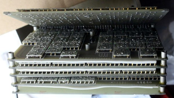
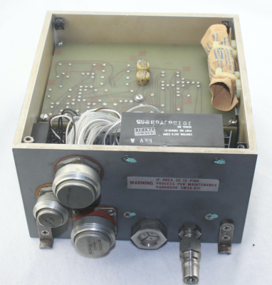
We’re unabashed fans of [Ken Shirriff] here at Hackaday, and his latest post about an Apollo-era transistorized shift register doesn’t disappoint. Of course, nowadays a 16-bit shift register is nothing special. But in 1965, this piece of Apollo test hardware weighed five pounds and likely cost at least one engineer’s salary in the day, if not more.

The incredible complexity of the the Apollo spacecraft required NASA to develop a sophisticated digital system that would allow remote operators to execute tests and examine results from control rooms miles away from the launch pad.

This “Computer Buffer Unit” was used to hold commands for the main computer since a remote operator could not use the DSKY to enter commands directly. Externally the box looks like a piece of military hardware, and on the inside has six circuit boards stacked like the pages of a book. To combat Florida’s notoriously damp conditions, the enclosure included a desiccant bag and a way to fill the device with nitrogen. A humidity indicator warned when it was time to change the bag.

There is a lot more in the post, so if you are interested in unusual construction techniques that were probably the precursor to integrated circuits, diode transistor logic, or just think old space hardware is cool, you’ll enjoy a peek inside this unusual piece of gear. Be sure to check out some of [Ken]’s previous examinations, from tiny circuits to big computers.

The Cardboard Computer

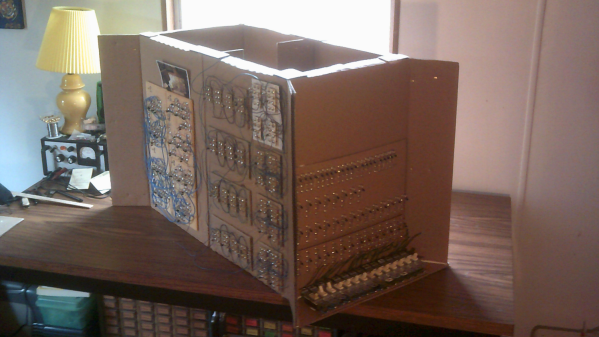
Every time we say “We’ve seen it all”, along comes a project that knocks us off. 60 year old [Mark Nesselhaus] likes to learn new things and he’s never worked with hardware at the gate level. So he’s building himself a 4-bit Computer, using only Diode-Transistor Logic. He’s assembling the whole thing on “card board” perf-board, with brass tacks for pads. Why — because he’s a thrifty guy who wants to use what he has lying around. Obviously, he’s got an endless supply of cardboard, tacks and Patience. The story sounds familiar. It started out as a simple 4-bit full adder project and then things got out of hand. You know he’s old school when he calls his multimeter an “analog VOM”!

It’s still work in progress, but he’s made a lot of it in the past year. [Mark] started off by emulating the 4-bit full adder featured on Simon Inns’ Waiting for Friday blog. This is the ALU around which the rest of his project is built. With the ALU done, he decided to keep going and next built a 4-to-16 line decoder — check out the thumbnail image to see the rats nest of jumbled wires. Next on his list were several flip flops — R-S, J-K and D types, which would be useful as program counters. This is when he bumped into problems with signal levels, timing and triggering. He decided to allow himself the luxury of adding one IC to his build — a 555 based clock generator. But he still needed some pulse shaping circuitry to make it work consistently.

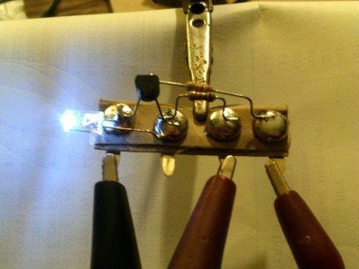
from right, Input, +5V, nc, gnd
LED Driver : from left, Gnd, NC, +5V, Input

[Mark] also built a finite-state-machine sequencer based on the work done by Rory Mangles TinyTim project. He finished building some multiplexers and demultiplexers, and it appears he may be using a whole bank of 14 wall switches for address, input and control functions. For the output display, he assembled a panel using LED’s recovered from a $1 Christmas light string. Something seems amiss with his LED driver, though — 2mA with LED on and >2.5mA with LED off. The LED appears to be connected across the collector and emitter of the PNP transistor. Chime in with your comments.

This build seems to be shaping along the lines of the Megaprocessor that we’ve swooned over a couple of times in the past. Keep at it, [Mark]!

Continue reading “The Cardboard Computer”

Hackaday Prize Entries: Inventing New Logic Families

One of the favorite pastimes of electronics hobbyists is clock making. Clocks are a simple enough concept with a well-defined goal, but it’s the implementation that matters. If you want to build a clock powered only by tubes and mains voltage, that’s a great skill tester. A relay-based timepiece is equally cool, and everyone should build a Nixie tube clock once in their lives.

For [Ted]’s Hackaday Prize entry, he’s building a clock. Usually, this would be little cause for celebration, but this is not like any clock you’ve ever seen. [Ted] is building this clock using only diodes, and he’s inventing new logic families to do it.

Using diodes as logic elements has been around since the first computers, but these computers had a few transistors thrown in. While it is possible to make AND and OR gates using only diodes, a universal logic gate – NANDs and NORs – are impossible. For the computers of the 1950s, that means tubes or transistors and DTL logic.

For the past few years, [Ted] has been working on a diode-only logic family, and it appears he’s solved the problem. The new logic family includes a NOR gate constructed using only diodes, resistors, and inductors. The key design feature of these gates is a single diode to switch an RF power supply on and off. It relies on an undocumented property of the diodes, but it does work.

Although [Ted] can create a NOR gate without transistors — a feat never before documented in the history of electronics — that doesn’t mean this is a useful alternative to transistor logic. The fan-out of the gates is terrible, the clock uses about 60 Watts, and the gates require an AC power supply. While it is theoretically possible to build a computer out of these gates, it’s doubtful if anyone has the patience to do so. It’s more of a curiosity, but it is a demonstration of one of the most mind-bending projects we’ve ever seen.

You can check out a video of the diode clock below.

Continue reading “Hackaday Prize Entries: Inventing New Logic Families”

Gates To FPGAs: TTL Electrical Properties

On the path to exploring complex logic, let’s discuss the electrical properties that digital logic signals are comprised of. While there are many types of digital signals, here we are talking about the more common voltage based single-ended signals and not the dual-conductor based differential signals.

Simulated "Real Life"
Single-ended Logic Signal

I think of most logic as being in one of two major divisions as far as the technology used for today’s logic: Bipolar and CMOS. Bipolar is characterized by use of (non-insulated gate) transistors and most often associated with Transistor Transistor Logic (TTL) based logic levels. As CMOS technology came of age and got faster and became able to drive higher currents it began to augment or offer an alternative to bipolar logic families. This is especially true as power supply voltages dropped and the need for low power increased. We will talk more about CMOS in the next installment.

TTL was a result of a natural progression from the earlier Resistor Transistor Logic (RTL) and Diode Transistor Logic (DTL) technologies and the standards used by early TTL became the standard for a multitude of logic families to follow.

Continue reading “Gates To FPGAs: TTL Electrical Properties”