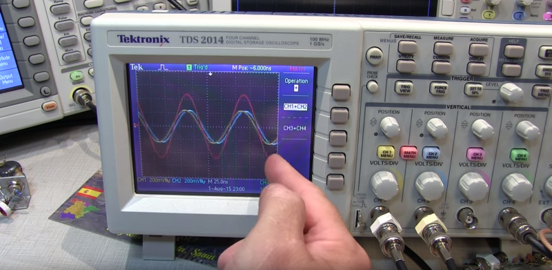
Standing waves are one of those topics that lots of people have a working knowledge of, but few seem to really grasp. A Ham radio operator will tell you all about the standing wave ratio (SWR) of his antenna, and he may even have a meter in the shack to measure it. He’ll know that a 1.1 to 1 SWR is a good thing, but 2 to 1 is not so good. Ask him to explain exactly what a standing wave is, though, and chances are good that hands will be waved. But [Allen], a Ham also known as [W2AEW], has just released an excellent video explaining standing waves by measuring signals along an open transmission line.
![[Source: Wikipedia]](https://hackaday.com/wp-content/uploads/2015/08/350px-standing_wave_2.gif)
All well and good, but what do standing waves actually look like in a transmission line? [Allen] obliges with a demo using a strip line, which is simply an open section of transmission line. With a special RF detector probe, [Allen] is able to sweep along the strip line and show a few cycles of the 2.4GHz standing wave generated by removing the line terminator. The nodes and anti-nodes are clearly separated on the strip line by a distance proportional to the wavelength.
For me personally, this was a real eye-opener. Now I not only understand where the standing waves come from, but that the nodes and anti-nodes map to physical locations on a line that are characteristic of the frequency of the standing wave. Simple concept, but without that visualization, it just never clicked. For even more eye-opening, be sure to check out [Eliot Williams’] recent “Say It With Me” column on input impedance.


Hey, cool! I made it on Hackaday!
Yep, long time ago, and many time since then.
I really, really love your Youtube channel, thank you very much for such a high quality material!
Here’s a brilliant demo for getting an intuitive feeling for wave behaviour. May have originally seen it here, can’t remember.
https://www.youtube.com/watch?v=DovunOxlY1k
Yes, I love this video – brilliant!
I have yet to watch this video, I’m keen to, but can’t right now. I just wanted to post this article I read back in 2012. It gave me a far greater understanding of waves than I ever have before. His contraption to show waves is brilliant. I’m sure it would complement this video nicely.
http://hackaday.com/2012/12/02/retrotechtacular-similarities-of-wave-behavior/
Actually 2:1 is not so bad, many even call it reasonable on some antennas it’s when you get to 8:1 that things get really sticky. Some Antennas by design are considered really well tuned at 2:1 In fact the G5RV is designed to have a bad SWR as it uses the feedline as part of the radiation pattern. A choke and an antenna tuner is required for that antenna.
Thanks, mr. W2AEW!
Agree – his Reflections book is really good.
Very Well Done!! Thank you.
Whwn it really gets interesting is with a signal that swings above and below zero.
You use various taps and a curved transmission line and create a compleatly solid state rectifier.
Whwn it really gets interesting is with a signal that swings above and below zero.
You use various taps and a curved transmission line and create a compleatly solid state rectifier. Of course the hard part is keeping a stable in phase signal.
Wait, what? Isn’t that any AC signal? Can you explain? This isn’t something I’ve run across before, and I’d like to learn more…
Awesome, subscribed!
Is it possible to create a standing wave in free space by putting an 1/4 wavelength isotropic antenna next to a reflector at say 850 MHz ????