[Radical Brad] has played around with FPGAs, video signals, and already has a few astonishing projects of bitbanged VGA on his resume. Now he’s gone insane. He’s documenting a build over on the 6502.org forums of a computer with Amiga-quality graphics built out of nothing but a 65C02, a few SRAM chips, and a whole pile of logic chips.
The design goals for this project are to build a video game system with circa 1980 parts and graphics a decade ahead of its time. The video output is VGA, with 400×300 resolution, in glorious eight-bit color. The only chips in this project more complex than a shift register are a single 65c02 and a few (modern) 15ns SRAMs. it’s not a build that would have been possible in the early 80s, but the only thing preventing that would be the slow RAM chips of the era.
So far, [Radical] has built a GPU entirely out of 74-series logic that reads a portion of RAM and translates that to XY positions, colors, pixels, and VGA signals. There’s support for alpha channels and multiple sprites. The plan is to add sound hardware with support for four independent digital channels and 1 Megabyte of sample memory. It’s an amazingly ambitious project, and becomes even more impressive when you realize he’s doing all of this on solderless breadboards.
[Brad] will keep updating the thread on 6502.org until he’s done or dies trying. So far, it’s looking promising. He already has a bunch of Boing balls bouncing around a display. You can check out a video of that below.


Will you be releasing schematics ?
Yes, I will be doing a dedicated website for this system, which will include schematics, PCB files, and a downloadable 300-400 page book on how every single part of the system works.
I will also include many source codes for games and demos.
Cheers,
Radical Brad
Dear Brad,
Please, is you book finally available?
I’m passinated about 8bit computers electronic and will love to learn from your work.
Kind regards,
Richard
Having a day job as well as a farm means that I only have the dead of winter for my electronics projects.
I have however, been continuing this design, evolving it more towards retro while at the same time adding a LOT more graphics power. The project now generates an NTSC screen with 8192 colors (twice the Amiga HAM mode).
The project also plugs into the cartridge port on a VIC-20, my favorite retro computer.
One day when I have more time, I will add a much more detailed build log to my site, someplace on http://www.atomiczombie.com
Brad
Thank you for your kind answer Brad.
I follow your work since the begin, I know that is a hobby and it is why I ask that only 3 years later.
I personally does little projects on my free time, so I understand. I would like again to build my own simple low res (around 320×200) GPU for my 8-bit computer mainboard, it is why I have looked again from your side. :)
Please, have fun with all your projects, I love what you do on your website.
Richard
Like that… going through this gives sound understanding of what digital is in its core… Today we are often so far away due to the VSLI(ntegration), that we forget to appreciate what we have and how ‘easy and powerful’ (digital) hacker life is…
“Every IC on this board is just 7400 logic!”
But there is an atmel MKII programmer connected to an AtMega 40=PDIP !
If I had to guess, I would say it’s doing ROM emulation or he is using it to preload RAM with code to speed his development cycles. The 6502 clearly needs some persistent code storage and a ROM wasn’t called out in the BoM.
Read the blog postings (long but insightful) – the ATMega is there for testing the GPU circuitry. It will not be present in the final version.
Hog wash. If Radical Brad were truely my hero, he would abandon this trivial puny project and write a Verilog to 7400/4000 synthesis tool that would place and route to minimize chips and a fitter that area optimizes chip placement in the form of a EDA board file output! Then Zeus himself would rain down a thunderclap when the 6502 too was replaced by an `include “6502.v”
Next time, dude!
Brad
Nitpick: A transparent color is not an “alpha channel”, it’s a specific color index that the hardware interprets as “let through whatever is behind this pixel in this sprite”. An alpha channel would mean either alpha blending, or even a specific bit in the sprite’s color data that flags the pixel as being fully transparent. A specific color index that inhibits a color write is not, nor has it ever been an “alpha channel”.
To be precise, the animated objects on the screen are not “Sprites” but “Bobs”.
https://en.wikipedia.org/wiki/Blitter_object
That’s debatable. A bob is by definition drawn using a blitter. Unless that pile of 74-series logic chips possesses a command set that I’m not aware of, they’re standard sprites. They’re no more bobs than the sprites of classic arcade games in the late 70’s and early to mid 80’s that were also drawn with standard 74-series logic and not ASICs.
Part of the project includes a simple blitter, yes. Here’s a description: http://forum.6502.org/viewtopic.php?p=38861#p38861 He uses the 6502 CPU to set up each blitter transfer.
Sorry, that was the first iteration. Here’s the new design. http://forum.6502.org/viewtopic.php?p=39196#p39196
As you can see from the yellow outline, the blitter actually takes up more space than the display generator.
I just like the name Sprite, reminds me of the C64. Bob or Blob sounds to drab.
Brad
I also see he is using the term “GPU” quite loosely.
Can you technically have a Graphics Processing Unit when your ‘unit’ is a gaggle of chips and wires on a bread board?
Its not the physical layout that matters, its the logical functions that count.
This is awesome beyond belief! Very nice work, [Radical Brad]!
Indeed, excellent (and very clean breadboarding) work!
For those who have not read the blog posts, I can highly recommend it… it gives much more insight into what is happening and why (and how he is using / abusing the various logic chips to do what is desired).
Thanks for the comments!
Since I made this video, I have expanded the board quite a bit, and increased overall performance.
I now have another 1024K doing a large scrollable bitmap transfers at the start of every frame.
This is called “The Playfield”, and can be 512×2048, 1024×1024, or 2048×512 in size.
I will probably start on the 6502 decode logic in a few days and then look for a dozen more breadboards to start prototyping the sound system. You can NEVER have a large enough board, dude.
Cheers!
Radical Brad
Hey shouldn’t you be off hacking bicycles or something? I was wondering what you’ve been up to ;-) (I’m aka “Rykoala” at that “other” site)
Yeah, doing electronics is just a way to relax on Sunday afternoons for me!
Once I have a garage back up, I will be hitting the welder again.
Radical Brad
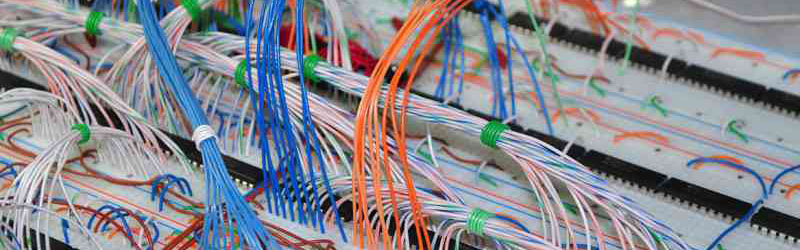
If he has any intermittent problems with his logic, the first thing I would do is to untie all the wrapped bundle of wires – that is just begging for cross-coupling of signals, especially on clock lines.
20MHz throughout the entire board and no glitches yet.
Wiring is wrapped us bus line bundles, with opposing signals kept at a fair distance from each other.
It’s more than just a pretty board, there is a small degree of sanity to the layout.
When I finally get around to making a real PCB, it will be easy.
Radical Brad
A word of caution – I ran into a problem with busses on a PCB when I did my first bit slice disk controller [AMD 2900 series around 1975] – I had the main 8 bit data bus running parallel to a r/s flip flop line which was next to a ground trace – every time more than 5 of the 8 lines transitioned from high to low, they would couple enough into the r/s flip flop line to reset the flip flop.
Very cool! Is there a description of the hardware sprites in any detail? I’ve just finished working out my FPGA VGA text mode, with the output being assembled from character rom, screen memory and attributes. I can see how you would do a bitmap display, shifting it out, but I don’t see how you would do arbitrary sprites in hardware without a silly number of registers… or is there some kind of copperish thing with the display asking the CPU if it wants a sprite on this line during the HBL?
+1, I would also like to see some schematics showing how the sprites are done.
I have started something similar with very small CPLD. It’s here –
https://hackaday.io/project/3610-z80-retro-computer-with-graphics
Where is your project [Howard Jones], Link please?
@[Brad] I ended up using the 800×600@50Mhz (72Hz) standard but at half clock – 400×300@25MHz because I had trouble finding 25.175MHz Active Oscillators and 50/100MHz are easy to find. My design is only a BMP like output – no sprites, so I would be very interested to see how you did the sprites. The really old retro games usually only had a background (often a scrolling image) a foreground image (for game play). The CPLD I am using has only about 400 registers.
And what did you do in a previous life to deserve this lol. Just jokes. I am easily able to resist the temptation of turning my CPLD design into a 74xx career.
I will have to write something up! The actual project is to try and get a proper old-school instant-on vt100 style serial terminal with one of those $30 CycloneII mini boards.
Having read some more of [Brad]’s thread, I can see that it’s actually more like an automated blitter assembling the back buffer before the display controller displays it. There’s a really nice write up of a similar design (but Xilinx FPGA not 74 logic) here: http://andybrown.me.uk/wk/2014/06/01/ase/
https://hackaday.io/project/7165-fpga-serial-terminal
Just a placeholder for the moment. I’ll update when I get some time next week most likely.
They aren’t really sprites, but Blitter objects. There are two video buffers, and while the display generator is showing the first one, the blitter copies rectangular objects into the second one. The CPU sets up the coordinates of each objects, and the address of the source data.
This requires much less complicated hardware than real hardware sprites. It does however require you to redraw the background for every frame.
By doing this, Brad knows more about programming and hardware than 90% of CS grads from all the worlds campuses.
Honestly This should be required for a CS degree.
Chuck Petzold’s “Code” is a great read for learning some of this stuff. Build a CPU out of relays (sort of). I agree that everyone should have *some* idea what the chip is actually doing.
What was the fastest SRAM available in the 1980’s? I found a datasheet for Intel D2147H 4096×1 bit with the fastest speed as 45ns.
Has me thinking of a line interleave mode with 2 banks of SRAM, with each bank holding half the lines – some way to effectively double the speed of the SRAM by using twice as much, using half the chips’ capacity and interleaving the cycles. During non-motion screens the display resolution could be increased by using all the SRAM in a single bank, non-interleaved mode.
Impressive project! However, the “design goal” seems a bit lost:
“The design goals for this project are to build a video game system with circa 1980 parts and graphics a decade ahead of its time.”
While it may use a 6502 and 74-logic – in case some are wondering why something like this wasn’t done back in the 80s. No they weren’t overlooking something: the real contraint of such a (gaming-) system in the 80s was memory. Memory was usually the single most expensive resource, and memory constraints were the reason backgrounds consisted of a block of indices into 8×8 pixel blocks, why color indexing (a palette) was used, ultimately leading to the more complex chips such as the VIC-II (C64), VDP (Sega), PPU (Nintendo), etc. These systems typically used only a few kilobytes of memory to create the full image. This was the “magical” thing these VDP’s did, as well as generating all this on the fly (including sprites) as the video trace flew by, without a framebuffer.
By removing this main constraint using today’s cheap memory, creating an image on the screen becomes a LOT simpler. This is why it can be done (as shown) using some 74-logic – you basically only need some counters to implement a crude form of DMA (copying blocks of memory from one location to another). It’s still impressive of course, but it’s important to view it in the right context.
Agreed, but there was also another edge to the sword. The CPUs of the era were not even 1MIPs. Having a large amount of video memory would result in the CPU being too slow to update it all. So other techniques like tiles were used. One tile was 32 to 128 Bytes of ram but the CPU only had to write one byte to change the tile. This gave the CPU quite some leverage over the Video RAM AND it requires less RAM to implement a frame.
If it were just the cost issue then there would have been some expensive computers with large video RAMs. There were some computers with more RAM like the Amega’s but they had a well designed system for the CPU to leverage time and also much faster CPU’s
Absolutely: the performance is of course another reason to use the tile-based approach, as you only have to update some indices, e.g. while scrolling. But as this example is using a 6502, I’m assuming he’s using it at a low frequency as well (like 1 or 2 MHz), so this is not something he ‘cheated’ on by taking advantage of the progress made there since the 80s. The other thing is performance of the memory itself, which was mentioned in the article. But what wasn’t really mentioned was the *amount* of memory, which is the most significant departure from the “design goal”, which is why I mentioned it above :) Not that you couldn’t have megabytes of RAM back in the early 80s: it just would have been very (and prohibitively, for a game system) expensive.
By the way, the Amiga had a blitter, which in a way is similar to the system designed here. And the Amiga could indeed do that because it had more memory.
Made a new video showing the next segment of the GPU working.
Try that on your Tandy, Andy.
https://www.youtube.com/watch?v=chACO3WNtg0
Cheers,
Radical Brad
Two more progress videos…
https://www.youtube.com/watch?v=3fXuFCxMHVI
https://www.youtube.com/watch?v=XuzK2BwvmKQ
Radical Brad
Do you have a block diagram of the GPU? Or even a schematic? I like it’s capabilities and it would be useful for a z80 project that I am doing.
Another video…
https://www.youtube.com/watch?v=HqSYwKYwtOo
The AVR is going to be external, so it is not part of the final design.
Cheers!
Radical Brad
Working on the Sound Generator now…
https://www.youtube.com/watch?v=fuJz3ERi8Kg
Radical Brad
*** MARCH 2019 UPDATE ***
This Project has been fully reloaded! See the final version come to life here…
https://www.atomiczombie.com/vulcan-74
There will be much more detail posted, regular updates, and full schematics and code.
Cheers!
Radical Brad
The beast known as Vulcan-74 is now taking on physical form!
http://lucidscience.com/temp/VC13.jpg
Check out the continuing build log here…
http://forum.6502.org/viewtopic.php?f=4&t=3329&p=78673
Cheers!
Radical Brad
HAD, please post this image of Vulcan-74….
http://www.lucidscience.com/temp/V74%20Concept%205.jpg
Can’t get image tags to work in a post.
Cheers,
Brad