One of the things that stops electronic devices from going faster is heat. That’s why enthusiasts go as far as using liquid nitrogen to cool CPU chips to maximize their overclocking potential. Researchers at Georgia Tech have been working on cutting fluid channels directly into the back of commercial silicon die (an Altera FPGA, to be exact). The tiny channels measure about 100 micron and are resealed with another layer of silicon. Water is pumped into the channels to cool the device efficiently.
A comparable air-cooled device would operate at about 60 degrees Celsius. With the water cooling channels cut into the die and 20 degree water pumped at 147 ml/minute, the researchers kept the chip operating about less than 24 degrees Celsius.
Even though water cooling isn’t a new idea, classical water cooling uses cold plates on the outside of the package, so they aren’t as efficient as the Georgia Tech method. By putting the water right at the source of the heat, packaging can be made smaller and it may even be possible to stack multiple chips without causing thermal management problems.
Higher speeds are only part of the story. Cooler electronics have less current leakage and longer device lives. Although the researchers were working with an FPGA, the technology is applicable to any integrated circuit that needs to get rid of heat. The research appears in a paper delivered at the 2015 IEEE Custom Integrated Circuit Conference.
Decapsulating ICs isn’t that hard, although removing the back part of the leadframe could be a problem. We have to wonder if an enterprising hacker will come up with a way to duplicate the feat in a garage, or–at least–something similar. After all, we’ve seen a water-cooled Raspberry Pi and LN2-cooled Arduinos.
By the way, if you are into PC overclocking, water is too mainstream. Even LN2 is too warm and the serious crowd is using liquid helium (see video below).
https://www.youtube.com/watch?v=AEYknrW33vo
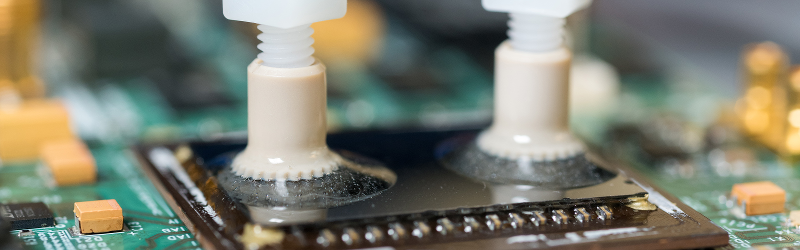
Photo credit: [Rob Felt]


In the proud hackaday tradition of “That’s cool, but…” I’ll say that this is really interesting (would like to see it applied to high power transistors) but I’m worried about moisture absorption over time. Also, if a channel gets clogged and a bubble of steam forms inside the die….
I wouldn’t be too worried about water absorption, considering the water is flowing though the back of the die (where there are no wires or other potential paths to circuitry) and the fact that it’s made out of silicon dioxide, which is pretty much glass/quartz. I wouldn’t expect the water to kill it quickly, if it did at all. As for clogging, I suppose the only defense is to cut large, clean channels, and ensure your water is clean.
Perhaps more so the packaging in terms of absorption, but I suppose that’s just a change to an epoxy that has a lower hygroscopicity…
At a lower die temperature, I’d be concerned about dew formation, especially in higher ambient temperatures. I guess that’s nothing that overclockers haven’t already had to deal with.
Anyway, neat.
Exactly. I would spend more efforts into a way to mount dies upside down into the chip, then leaving one surface of the (formerly) underlying metal tab exposed externally so it makes direct contact with the heatsink.
“metal tab”??? Direct silicon. Many chips are nowadays mounted “flip chip”. And then their “backside” becomes readily available for cooling. I changed the cooler on a video card less than a week ago. Cooler was directly in contact with the silicon die.
It’d be more difficult for power devices as they use the whole thickness of the die (they are vertical devices) rather than having an unused substrate (lateral devices) that can be modified with channels.
Not insurmountable though, if the channels are designed in at the start. This is probably more useful for microchips though, where high switching speeds create a lot of heat, particularly localised in tiny areas. You don’t get that with power transistors, etc, where the whole die does the same job, has roughly the same power passing through it, etc. Probably external cooling will be fine. And with a power device, you can always just make it bigger.
Worst video ever.
needs more vuvuzela
And quite a terrible job of it, too! Just pour the stuff on? I imagined some kind of self-contained closed loop system.
Nope. Competition overclocking is all about hitting a CPU frequency target for a few seconds, not running stable all day.
Years ago I used to run a 2.66 GHz Intel CPU at over 4 GHz once in a while, but it was never stable enough on air cooling to do that for extended periods of time. I turned it down to 3.6 GHz for everyday use. Then I got bored of overclocking and went on to other, more interesting hobbies.
those were the days
The evaporation is also taking away a lot of heat.
A lot of the skill is in getting bios settings right
it has to evaporate. do you have any idea of the condenser and compressor that would entail, i imagine fairly crazy
Heat pipes works that way without the complex compressors and condensers. They lower the boiling point by reducing the pressure.
totally agree, it’s the most uninteresting article I ever seen quite in a while at HaD. are we turning into engadget now??
You sir, haven’t seen the article about mechanical watches vs Apple watch. That was pure advertisement. Not even for the good devil.
Why would anyone want an Apple watch?
Why the hell does every video ever now have to have dance club beatz behind it? Who decided this?
whats with the recent off topic sponsored embeded youtube videos? Most annoying form of advertisement. I guess this is what happens when HaD sells out….
For the record, it is not sponsored at all. Just a random pick of liquid helium cooling on YouTube because I brought it up. I’d have like to have had video of the actual topic, but I haven’t seen any yet.
Oh, you are the writer for the other article that caused me to complain : http://hackaday.com/2015/10/05/the-worst-cad-package-ever-is-still-handy/
Its not like people do not know what liquid cooling or schematic entry programs are.
A bit suspicious that they are both branded videos by companies that I suspect having agreements with HaD. If only the FTC actually enforced disclosure requirements!
Sheesh, get a grip. Go put your tinfoil hat back on and find something better to complain about. No one is forcing you to read these articles or watch the videos. Even if it were sponsored, who cares? HAD is better than ever since Supplyframe came on board.
> Even if it were sponsored, who cares?
If we ever post *any* sponsored content without it being absolutely clear in its labeling, I’ll quit. That’s a promise. So, yeah, people (especially on the team) care if it’s sponsored or not. That’s not something to be taken lightly.
@Brian Benchoff: My apologies. I was referring to what WE as readers get for FREE on this site. It was in no way intended as a slight to you, your coworkers, nor your ethics. My intention was only to point out that the readers on this site pay nothing for the privilege and therefor should be grateful for what we get, sponsored or not.
Meh. Gotta pay the bills somehow. Better annoying ads than no Hackaday at all.
You don’t even want to know what I’d do for money. Me love you long time?
Do you want the annoying? Browse the youtube from my computer in my country. If they get it going, you will see an video ad after every two views. It has annoyed me far as not opening YT voluntarily and starting consciously avoid number of products.
This trend makes me very concerned as we are moving towards televication of the Internet. It actually would be worse as you will learn to be afraid to make a click.
You do want to help to take the fun out of the Internet? Randomly poping up video ads is your thing then.
You may want to try an addblocker. Don’t know if it will work in your country, but my AddBlockPlus (ABP) can strip advertising from both websites and youtube videos. Also, you can whitelist domains you want to support, i.e. because I like HAD, ‘hackaday.com’ and ‘hackaday.io’ domains are whitelisted in my ABP.
Why do you want to block one of the most common mathematical operations? Free the addition! No AddBlocker!
Little bit of tweaking, you can get rid of Wikipedia’s “Hey Guize, I need a new yacht” begging too.
If Wikipedia weren’t run by a cartel of spergs, and encourages this, and if it wasn’t for Jimbo, then maybe I’d give some money to a reputable encyclopaedia. I won’t start Wikigroaning but basically a real encyclopaedia plus a guide to every Anime ever produced would do the same job.
Instead of comparing these microfluidic passages to a standard heatsink/fan I would like to see how it compares to a standard water cooling setup. My guess is not as impressive a temperature difference.
I was thinking the exact same thing. Since water cooling is superior, I’d like to see as well.
It’s not really that good. A good waterblock might manage about 0.22 C/W, but that needs a proper contact with the CPU die. Simply slapping one on top of the plastic packaging of a FPGA won’t do.
Liquid cooling – when talking of equal heatsink surface areas – is actually worse than air cooling because it has more material interfaces that the heat has to cross and each discontinuity is analogous to a resistor to electric current. It offers more thermal resistance, but since the radiator can be many times larger it can handle more power.
In short, ordinary liquid cooling gets higher idle temps, but lower load temps than air cooling.
you may be right, but your explanation makes no sense and defies heat transfer science.
How?
Thermal resistance in materials is analogous to electrical resistance in wires, where temperature is analogous to voltage. The higher the temperature difference, the larger the heat flow, and the higher the thermal resistance, the higher the temperature of the CPU has to be to achieve the same heat flow towards the surrounding ambient air temperature.
In practice, at low loads when the surface temperature of a heat sink is very close to ambient temperature, the bottleneck for heat transfer is at the interface between the CPU and the heatsink. The liquid system just adds more interfaces with more thermal resistance before the heat gets to the actual heatsink (radiator) surface, and that makes the CPU idle at higher temperature.
When the load increases, the bottleneck becomes transmitting the heat to the heatsink surface along the thin metal blades, and from there to the surrounding air. There a liquid filled radiator is much more efficient than a regular heatsink – even with heatpipes- so the liquid cooling system has a higher baseline temperature, but it sheds more heat for a unit increase in temperature above the baseline.
And another practical concern is that liquid cooling pumps add another 10-15 Watts of heat into the loop just by the pumping losses.
I think an analogy for Dax’ description would be using a tiny (1/10W) 1 Ohm resistor to dissipate energy from a large capacitor (this is a small fin mounted on the die). If the voltage on the cap is small, this will work better than a larger (1/2W) 5 Ohm resistor (the fin doesn’t get saturated with heat). If the voltage on the cap is large, the tiny, lower-resistance part won’t cut it because it has a lower limit on how much power it can handle. The 5 Ohm resistor won’t be able to drain the charge from the cap as fast, but it can handle higher the power (this would be the larger, water-cooled system).
I think it is easy for people to forget that the water being used is not refrigerated; it is only thermally linked to the ambient air through a radiator. I think Dax is correct in his explanation.
Water has a higher heat capacity than air, and it’s denser. And you’re not limited to equal heatsink areas. What you are limited by, is the area in contact with the heat source itself, the chip. It makes sense to absorb as much heat as possible in the chip, and then dissipating it into the air is somebody else’s problem, and not a difficult one. This is why water cooling even exists.
I think this would be FAR more effective than regular water cooling, as you have far less thermal resistance in this setup. Here, heat is conducted directly from where it’s generated in the silicon substrate into the water flow. Comparing a typical cpu water-cooling setup, there is no heat spreader, the goop/solder in between the die and heat spreader, no thermal paste, no giant heat-sink/waterblock, AND there is a far shorter total path between where the heat is generated and where it’s carried away by flowing material.
Silicon dioxide dissolves in water, so it might not be the best idea.
What? SiO2 is glass…
Have you never seen a beach dissolve when the tide comes in?
This seems like it would clog very quickly. Water cooling systems form lots of crud and need regular cleaning. Even if that was not the case, particulates from the pump would probably grenade the chip much quicker than a similar air cooled part. Hasn’t IBM been working on this for a while?
http://thefutureofthings.com/3547-ibms-nano-water-cooled-chips/
That would depend on the quality of the water you’re using. The crud that comes out of a tap? Yes, that will clog things. Pure distilled water, not so much. There are other liquid coolants that have been developed specifically not to react or leave crud, and since the flow rate is low on this system the volume and cost may not be an issue.
Reminds me of this:
https://www.youtube.com/watch?v=miJbB9MTwzU
What if the manufacturers were to actually build this into the chips during fabrication?
exactly my though. honestly, why the hell wait for it to be made, instead of working in tandem with manufacturer?
I think that’s the idea. But until you’ve got it working, chip companies aren’t going to go to this huge amount of trouble and expense. Eventually of course chip makers will include the process, assuming it works. Nobody’s expecting to have to send their chips off to Georgia to have channels drilled in them.
It’s likely to crop up in PC CPUs first, since they’re the most expensive commodity chips I can think of, and will benefit a lot from better cooling.
That’s why a research institute is doing this kind of stuff. To test ideas, see if they work at all, and then allow industry to implement them in the next generation hardware.
So someone has managed to create a water cooling setup that’s supposedly different/superior and then compares his results with an air cooled setup instead of a traditional water cooling setup..
eh?
because it isn’t an internet dweeb overclocking study. It’s microfluidics work by real scientists who are not overly concerned with the performance compared to giant blocks of copper and oversized radiators, both of which are impractical and too expensive for large scale deployment. furthermore, if you don’t understand the benefits of this research you have insufficient heat transfer and manufacturing training.
and obviousy didn’t even bother to read the actual work.
“However, existing liquid cooling technology removes heat using cold plates externally attached to fully packaged silicon chips – adding thermal resistance and reducing the heat-rejection efficiency.”
In the article they make a reference to existing liquid cooling technology and go on to explain that it’s not so efficient because the ‘package’ tends to add to the thermal resistance.
That is a fair statement but should be backed up with an experiment to show that their setup is superior in that aspect otherwise why mention it in the first place?
Never did I claim or otherwise show a misunderstanding of the benefits of this research..
I always wanted to build a liquid coiling setup with a vortex tube. They work with water at like 20 BAR, and the diesel 12v methanol injection pumps reach that fairly easily for about $100.
2 radiators, pump, vortex tube, water block and a reservoir.
I definitely want to see someone try this. Cost of a chip aside (the chips that tend to get warm are also often the more pricey ones) this seems like it’d be fairly easy to build at home. Simply decap the underside of a chip and flow water through scored channels in the back. (not as good as the researchers did, but would yield interesting results) Perhaps someone could try this with a large power transistor and compare with a water block and some thermal paste?
In some ways easier because you’d have the heat spreader to work with instead of bare silicon. In fact, I wondered if just by exposing the heat spreader you could get some higher efficiency. No need to score it or anything. Like you say might not be as good as what they did but might be better than a classic solution. Of course, the big CPUs already do that. The chip’s face points “down”. with the pins and the metal at the top is somehow thermally connected to the heat spreader. Pretty good pictures here: https://en.wikipedia.org/wiki/Heat_spreader
Actually looking at the picture, maybe that’s what they did anyway. The FPGA is probably got the same arrangement. Delid the part and there’s the back of the die… hmm…. well… at least the heatspreader touching the back of the die… hmm….
I could see this method being applied to high power LEDs.
They really should just start using a synthetic diamond substrate for these chips, since it has 5x the thermal conductivity of silicon. Then add extra cooling around the edges, in contact with the substrate.
Come to think of it, I wonder if Intel has done competitive studies of adding thermal vias in the form of posts of metal on the interior of the the die that can facilitate heat removal via substrate or superstrate (obviously sacrificing something in terms of wafer area and layout effort).
I have seen small chips burn up real diamonds. The answer was two chips running an on/off cycle. They run long enough to get the mission accomplished.
let’s not forget http://www.bbc.com/news/science-environment-24571219
There are systems that run in silicon oil (coolinol 35). The system is totally enclosed and the oil circulates thru the components and out to a heat exchanger before returning to the components. Thermal expansion chambers are
required. I believe a system is available for cars also.
“There’s a great future in graphene. Think about it. Will you think about it?”
-Mr. McGuire from the re-make of “The Graduate”
“The Unemployed Graduate”
Who is getting laid, so it’s actually Sci-Fi.
You missed out ” / Fantasy”.
i think thats not very efficient. Water has a higher thermal resistance than metal, thats why water-cooling setups first spread the heat with a metal cooler and then transfer the heat to the water over a large surface. so silicon->metal->water->metal->air. water has a lower thermal resistance than air so you can build smaller heat exchangers on the processor side.
So all in all if you would try to cool your cpu with direct water contact it would be MUCH more inefficient then you metal and water/air. The energy density is just to huge. Years ago i saw someone tried this with his athlon cpu and got to the same rsults. cant find it anymore.
EDIT: “then you metal and water/air” -> “the USING metal and water/air”
Yeah but in this case the water moves, where metal is static.
It makes no sense that transferring the heat through metal first, then into water, is better than going straight to the water to start with. Yes, water is less thermally conductive, but that doesn’t matter. What matters is getting coldness to the chip. Pumping continually cooled water does that. It doesn’t have to meander through a great big heat sink. You’re going straight from heat source to coolant, no middle men. No heat sink to warm up and keep the heat from being pumped away quickly.
Once you have the hot water, what to do with it is a separate problem, not part of this at all. The assumption is that a supply of cold water is available. Running it through a loop and a radiator is no problem. The radiator can of course be any size you like, since it doesn’t have to fit in any casing or on top of any chip package. Talking about a PC’s CPU in particular.
1.) Jerry Presentation.
2.) Potato Phone Pics.
3.) No process outline to DIY.
4.) How do we get DARPA cash to fart around and break/build/putz around with “free” high-end chips?
Since details are omitted… Out on a limb, high res x-ray/MRI? Hmm. X-ray would zonk/wipe the chip. MRI/Ultrasound? Possibly bust the tamper proofing if any.
Chilled Mineral oil bath and CNC router submerged shaving at high rpm and low transition speed to find the space to run the channel. Possibly find the point where one could laser line decap/delid.
Pure water having zero conductivity. Okay. Big deal.
If you have the right tools and right approach you can do almost anything.
Including transmute peanut butter into gold.
You could always x-ray one chip, then throw it away. The others are gonna be just the same. Tamper proofing would be a pain, presumably there’s an FPGA without it, and that’s what they use. It makes sense to only add tamper-proofing to chips that need the security, and then charge more for it.
Valid assertion. Now, had they said “oh we used high powered, (with maximum width the of wavelength photon IR on one channel) a chamber that was pressured to 100-300 psi and strobe flash cut the top off similar to flint-knapping I would have been impressed.
Make a 3d printed mobo and pc parts where the hotter it gets the colder it gets as the exxess heat gets transferred over to the battery on the devices.