I’m always a little surprised that we don’t see more ARM-based projects. Of course, we do see some, but the volume isn’t what I’d expect given that low-level ARM chips are cheap, capable, low power, and readily available. Having a 32-bit processor with lots of memory running at 40 or 50 MIPS is a game changer compared to, say, a traditional Arduino (and, yes, the Arduino Due and Zero are ARM-based, so you can still stay with Arduino, if that’s what you want).
A few things might inhibit an Arduino, AVR, or PIC user from making the leap. For one thing, most ARM chips use 3.3V I/O instead of the traditional 5V levels (there are exceptions, like the Kinetis E). There was a time when the toolchain was difficult to set up, although this is largely not a problem anymore. But perhaps the largest hurdle is that most of the chips are surface mount devices.
Of course, builders today are getting pretty used to surface mount devices and you can also get evaluation boards pretty cheaply, too. But in some situations–for example, in classrooms–it is very attractive to have a chip that is directly mountable on a common breadboard. Even if you don’t mind using a development board, you may want to use the IC directly in a final version of a project and some people still prefer working with through hole components.
The 28 Pin Solution
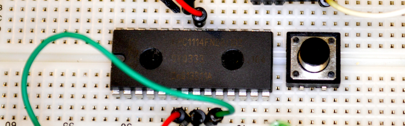
One solution that addresses most, if not all, of these concerns is the LPC1114FN28 processor. Unlike most other ARM processors, this one comes in a 28 pin DIP package and works great on a breadboard. It does require 3.3V, but it is 5V tolerant on digital inputs (and, of course, a 3.3V output is usually fine for driving a 5V input). The chip will work with mbed or other ARM tools and after prototyping, you can always move to a surface mount device for production, if you like. Even if you are buying just one, you should be able to find the device for under $6.
I recently wanted some breadboard setups for students. I did end up make a simple PCB that plugs into a breadboard, but looking back the simple circuit would have worked just as well placed directly on a breadboard. Here’s what you need:
- An LPC1114FN28
- A 3.3V power supply
- A 3.3V or 5V USB to serial cable or adapter
- One or two 220 ohm resistors (not absolutely necessary)
- An LED and suitable resistor (optional)
- Two 0.1uF capacitors (not absolutely necessary)
If you have a USB cable that puts out 3.3V, you can probably drive the chip directly with that. Otherwise, you can use an LD1117-3.3 or an LM7833. A bench supply or one of those cheap power supplies that plugs into a breadboard will work too. Just remember, the chip needs between 1.8V and 3.6V to operate.
Building the Hardware
The circuit is so simple, you almost don’t need a schematic. Here’s one anyway:
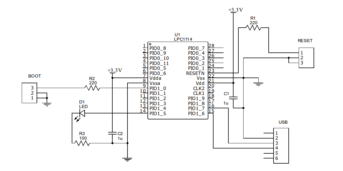
One reason that this works so well is the chip has a built-in serial bootloader. If you short the PIO0_1 pin to ground and reset the chip, you can easily upload a program to the device. You could probably get away with just shorting both pins to ground (they are internally pulled up). However, I like to put a small (220 ohm) resistor in series in case software is driving the pin as an output for some reason.
Of course, the jumpers (BOOT and RESET) and connectors in the schematic can just be breadboard wires if you don’t want to mount actual pins. The USB “connector” assumes that pin 2 is ground, pin 3 is the PC’s receiver and pin 4 is the transmit (that is, the LPC1114 talks on 16 and listens on pin 15). If that doesn’t match your cable or RS232 converter, change it as needed.
You may also want to adjust the value of the resistor depending on your LED, but you aren’t making a flashlight, so any value that will get a visible glow ought to be fine (or, omit it completely if you don’t want to blink an LED). If you are a real minimalist, you could dump the 220 ohm resistors, too. The capacitors help decouple your power supply, but breadboards have a good bit of capacitance already and if you have a clean supply, you might not need those either.
So if you have a breadboard and a USB to serial adapter, you could build the bare bones version of this for about $6 and maybe break the bank at $15 if you had to buy everything. Of course, if you have another ARM programmer/debugger that you want to use, that could be wired up instead of the USB cable. But I’m guessing if you have that kind of hardware, you’ve already solved your breadboarding problem.
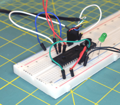 Here’s my (almost) bare bones version:
Not pretty, but effective. I used a switch for the reset and just a wire for the boot jumper. The LED has an internal 5V dropping resistor, but works fine at 3.3V (and I dropped the other two resistors and the capacitors). To work through the software example below, you’ll either need another LED connected to pin 1, or you can just lift up the connection on the breadboard and repurpose the LED. Be aware though: The mbed code assumes you have an LED connected to pin 14 and will blink it if it finds run time errors. If you move the LED you could have an error and won’t get an indication.
Software
You can use any ARM tool chain that can generate code for the LPC1114. There are plenty to choose from, but I’m going to assume you are just getting started, so let’s use the mbed web site. I’ve covered how to program using mbed before, and you might want to check out the video below for that walk through.
Here’s a quick summary of the steps you’ll need to take:
- Go to http://developer.mbed.org
- Create an account if necessary and log in
- Click on Platforms and find LPC1114FN28 (or go directly to the page)
- Click Add to Your mbed Compiler–if you see a button that says Remove, you’ve already done this
- Now head to the project page and import the project
- Compile the project and download the BIN file
Once you have the BIN file you’ll need to upload the program via your serial port. I’m going to use a utility called lpc21isp to do that. You can usually find this in your Linux repository, and there is a Windows version available, too. If you just hate the command line, you can always use FlashMagic or the official NXP Windows downloader. There are some GUI front ends for lpc21isp, too, but it is simple enough to use the command line.
The file you’ll download from the mbed website will be named HaD1114Demo_LPC1114.bin unless you changed it (I’ll assume it is in directory /tmp). You also need to know the name of your serial port (e.g., COM1 or /dev/ttyUSB8). The last thing you need to know is roughly what clock frequency the CPU is using. In our case it is 48MHz. Here’s the command line:
lpc21isp -verify -bin /tmp/HaD1114Demo_LPC1114.bin /dev/ttyUSB8 115200 48000
You want to engage the boot jumper and reset the chip either right before or right after executing that command line. The 115200 sets the baud rate and the 48000 is required so the software can sync with the bootloader.
Once you get a successful download, lpc21isp will tell you it is launching the new code. Don’t believe it — It isn’t doing anything yet. You’ll need to disengage the boot jumper and then reset the CPU again. If you prefer to do just a blinking LED, start a new project and that’s one of the boilerplate examples you can use in a new project.
Inside the Code
The code is simple. Just like the Arduino has a lot of helper library routines, mbed provides most of what you need to drive the devices on the CPU. There’s also an active community of shared libraries for external devices and example code. Here’s the simple code used for the demo:
#include "mbed.h"
PwmOut myled(dp1);
int main()
{
 int i,j;
 while(1)
 {
 for (j=0;j<2;j++)
   for (i=0;i<1000;i+=10)
    {
    float pwm=i/1000.0;
    myled=j?1.0-pwm:pwm;
    wait(0.01);
    }
 }
}
The mbed library frequently makes use of floating point numbers. In the example code, the PWM range is from 0.0 to 1.0. The wait call uses seconds, so 0.01 is 10 milliseconds (there is a wait call that takes a millisecond value, by the way).
The j loop keeps track of even or odd passes so the PWM gets reversed on alternate passes. When j is zero, the PWM goes from 0 to 1.0. When j is not zero, the steps go from 1.0 down to 0. Each pass requires 100 steps (0 to 1000, counting by 10s) so the total time per pass is about 100 times 10 millisecond, or one second.
What’s Next?
The mbed library is one place to start, and you can read its documentation online. If you are tied to the Arduino library, there is a port on Github (although I haven’t tried it). However, you can step up to bigger tools and even debugging when you are ready (there’s a good set of examples on Digikey’s eewiki, or you can keep using mbed with your own IDE and debugger). If you want a quick rapid prototyping arrangement, this set up will easily run a pretty nice Forth, too. And if you are concerned that this isn’t really a hack, you could always chop the chip down to size literally (although we don’t recommend it).


I’ve always been surprised people pick Arduino over little Arm cores. There is a ton of code out there for Arms just like there is for Arduino. Personally as long as you can get the toolchain set up then I like the little F051 discovery boards by STmicro. Has a ton of features for an $8 to $9 board.
+1
I have really been enjoying the new msp432 by TI. Its nice having an Arm M4-f with its 32 bit floating point witchcraft in a package that uses less power than most popular 8 bit micros
+1 for MSP432
Worth noting it’s an ARM M4F core and supporting hardware, with MSP430 based peripherals. The LaunchPad version is supported by Energia, an Arduino-like environment, which puts down a version of TI-RTOS to it so you can multi-task sketches fairly easily.
The reason is that an Arduino is a microcontroller. This means it has lots of peripherals onboard that are designed to interact with the outside world – ADC, UART, I2C, Digital I/O with pullups/pulldowns, PWM controllers, timers and more. By comparison traditionally a CPU was just a processor core only, and required additional components.
The lines are blurring with ARM SoC units, but the differentiation still exists for a reason.
Arduino is a hardware/software ecosystem, not a microcontroller. These ARM parts are microcontrollers, also, so I’m not sure what you mean by this distinction. The CPU is an ARM (ARMv6 or ARMv7/v7E depending on the Cortex series), while the microcontroller on (most) Arduino boards features an AVR CPU.
The Raspberry Pi ARM microprocessor SOC (BCM2835/6) also has PWM, Timers, GPIO, UARTs, SPIs and I2C peripherals in the same vain as microcontrollers. The lines between microcontrollers and microprocessors blur only when you look at peripherals..
It’s pretty well defined if you look at whether the CPU core has a Memory Management Unit (MMU) and whether it can run an Operating System like Windows/Linux which uses the MMU to perform memory mappings between virtual and physical addresses. If this is the case then it’s definitely a microprocessor otherwise…it’s a microcontroller.
I sometimes notice that some people mean ‘ARM microprocessors’ when talking about ‘ARM cores’. This is not necessarily true.
ARM cores can be:
i) Microprocessor-based…the Cortex -A family (A5,A7,A8,A9,A15,A53,A???) …used in smartphones, Raspberry Pi, beaglebone blacks, routers, Linux/Android SBC’s e.t.c
ii) Microcontroller-based…with the Cortex-M family (M0, M0+, M3, M4, M4F, M7). These variants are the targets of this article. I believe there’s also a Cortex-R family of ARM microcontrollers intended for safety critical real-time applications…but I rarely see these variants discussed in the hobbyist community.
Uh. The difference between a microprocessor & a microcontroller has nothing to do with having an MMU. In general (there can be some overlap) the difference is that microcontrollers have built-in RAM, ROM & I/O, while microprocessors don’t. The rule of thumb is that if it’s possible to build a useful gizmo out of it without adding any other chips, it’s a microcontroller.
It’s because Arduino is absolutely everywhere and you can be spoon fed. and I understand the attraction. any time I find someone interested in getting in the hobby I point them directly at an Arduino as there is a metric ton of tutorials, howto’s and setting up to write and compile takes zero efforts no matter what platform computer they have.
Working out of the box, FIRST TIME, is a very rare and valuable thing. Often tools of whatever nature need tweaking, they’re made by people who already have a full understanding of the system, and forget about the assumptions implicit in what they do.
Being able to know absolutely, literally nothing about electronics and programming, and being able to construct an Arduino project in however many days, is a miracle. And unlike many other “miracles”, and this is the most important thing, it delivers.
No little tweaks, no “fixes”, no “you have to have xxx”, just plug and literally go. It’s easier than installing some software, and you get tangible results. Of course, from there, you learn, and your abilities grow. But being suitable for a beginner, and doing what it’s supposed to, is the key. No hours trawling the net and giving up. You probably won’t even swear once!
I’m a beginner with no programming experience and Arduino is my first and only choice because it seems much more accessible. I would love to try ARM or AVR programming but the learning curve seems steep.
The Arduino IS an AVR! Except the ones that are ARMs. Far as I know, the chip doesn’t make a difference, they run the same code, and the software manages the different compiling needed. You might not even know if you’re using an ARM.
Thanks!
You’re welcome! Of course the thing about running the same code only applies if they’re both in Arduinos, running the Arduino system, software etc.
That said, much microcontroller programming is done in C anyway. Some code would be transferrable across any processor. But things like on-chip peripherals, and other hardware issues, require some different programming, and of course on the small chips you don’t have a lot of RAM to store variables, so you have to take that into account.
Even on Arduino you need to know what hardware your chip has, but it’s quite well taken care of, not as complex as it could be, thanks to the libraries including the necessary code and keeping it fairly simple. Like I said in a previous post, it’s great how Arduino just works, simple as that!
ARM support in Arudino only left a long beta ~6 months ago.
mBed is a fine idea, but kind of a messy ecosystem. And whoever makes the core libraries *way* over-does the C++ fanciness.
When it comes to 32 bit microcontrollers in DIP packages, Microchip’s PIC32 line (based on the MIPS architecture) can’t be beat. They have at least half a dozen different choices in 28 pin DIPs, and several of them include built-in USB interfaces. They also offer more memory than the LPC1114, and they’re 0.3″ wide instead of 0.6″.
They also have a free, manufacturer-supported tool chain with no code size limitations.
I tried using ARMs, but between the PIC32 DIP chips and the free tool chain that I didn’t have to cobble together piecemeal, I switched to PIC32.
“Microchip’s PIC32 line (based on the MIPS architecture) can’t be beat.”
Yes they can and have already been beaten by ARM’s.
ARMs have beaten PIC32 in the general market. But I qualified my statement with “in DIP packages”. There are lots of ARM uC manufacturers and there is a grand total of one ARM chip in a DIP package. There are 20 PIC32s in DIP packages, and they have more memory and features than the LPC1114.
For hobbyists who want 32 bit microcontrollers in DIP packages, PIC32 is the better choice.
I agree with you Bob
One can get PIC32MX250F128B and program it with ChipKIT DP25 bootloader and use it with breadboard and MPIDE or UECIDE. I even found that chip at tme.eu preprogrammed with DP25 bootloader for less than 4 dollars.
There is also the LPC810 8-pin DIP that I use.
But I agree with you that those 2 are the only ones.
I like the PIC32 also, one thing I love is the additional RAM/Flash. I don’t need speed as much as I need more resources for networking, higher layer protocols and encrypted communications. I haven’t started really worrying about power usage yet but I guess that will come after I finish working the encryption.
I could care less about DIP packages. If I want to put an SMD part on a breadboard/perfboard, 9/10 times there’s a $3 generic breakout board available with the correct footprint and 1/10 times I can whip up one in eagle and get it from OSHpark in a few weeks. if the part already has a following, chances are adafruit or sparkfun sells it already mounted on a breakout.
Microchip has a free IDE that is pretty good, supports all chips, with no sign-up and no code size limit.
That goes A LONG way.
I hate PIC micros with a passion. But emotional baggage aside, they lack a decent free toolchain.
No and 2 main reasons :
– PICs come with no pre-programmed Bootloader.
-The toolchain is EXPENSIVE.
I wish it was not the case though :/
microchip does not sound ‘maker friendly’. their toolchain has issues, its not free, its not gcc-based, it varies a lot based on which chip type you use.
PIC could have been the arduino darling but they did not want to be that open. and so, I actively avoid PIC.
I will get into ARM eventually but I have zero interest in doing PIC work unless I’m being paid and given the tools for free.
their corp view is just not compatible wtih free software. since they are not the only player, I don’t have to agree to their rules. I’ll use other chips.
I routinely use SDCC for 8-bit PIC micros and MIPS GCC for PIC32. It is completely open source, actually both compilers are built from sources on my Linux machine. I program it using open-source PicKit2 programmer (developed by Microchip).
To me, their products are quite open-source friendly. What am I doing wrong?
On the other hand, Microchip doesn’t care much about open-source world (with a few exceptions, like PicKit2), this is mostly volunteers work. Microchip is a big company interested in big bucks, just like Atmel or NXP.
I like the PIC. But my whole point (not just to [jaromirs]) is that if you are working with things like Arduino there’s a lot of reasons you might not want to move up to 32 bit: toolchain set up, SMD, cost…. and so my point here is that this is a gateway drug. Costs too much. Nope. Hard to set up the tools. No. I don’t want to deal with SMD. No problem.
After you get going, you are going to think… “Well… I ought to do a real IDE so I can debug.” Then later you’ll say, “Eh… I guess I should get an SMD part on an adapter board.” But you’ve already got sucked in.
Granted PIC has a lot of package options and can be cheap. But the toolchain is not plug and play (to start) with the rich library/community support you find with Arduino or mBed.
But sure, for those of us who deal with SMD and are used to setting up toolchains, you can take your–no pun intended–pick. I use lots of different processors, but my point here was if you are clinging to an 8 bit Arduino, there are other options (including, of course, the newish 32-bit Arduinos).
Thinking like a salesman overcoming objections ;-)
Al Williams: point taken and I have to agree.
I made my transition to MCUs yars ago, so my point of view is different to that young player with Arduino in his hands and the Arduino (or mbed) ecosystem have much more sense to them, while being not that important to me. I just wanted is to correct the info that you can’t have free and open-source tools for Microchip MCUs. Seems like a lot of people don’t know about it. Another inspiration for next hackaday.io project: how to set up open-source toolchain for Microchip MCUs.
It is fantastic world we live in. So much hardware platform to choose from :-)
You can buy PIC32 with chipkit bootloader preprogrammed, though there is not PIC32 with internal bootloader in ROM.
Toolchain is for free. Can’t be any cheaper. Anyone can avoid Microchip’s toolchain and use MIPS GCC to program PIC32, just like ARM GCC is used to program 32-bit LPC or STM32. Just like chipkit is doing with their PIC32 “arduino compatibles”.
Do you need a Pic-Kit to program a PIC? Could an Arduino you already have be pressed into service? Since Arduinos are much cheaper than Pic-Kits, and often what somebody starts off with, would seem sensible. And I’d guess Pic-Kit itself uses an MCU. Presumably a PIC.
PicKit2 is programmer/debugger – quite handy tool – just like AVR dragon. Unlike it, it is fully open-sourced by Microchip and chinese clones, sold for something like 15 bucks are quite good. But there is more than one way to particular goal.
I’m pretty sure I’ve seen programmers for both 8- and 32-bit PIC micros built around arduino. The programming algorithms are open, I made a few PIC programmers before, it is not very difficult task.
Except for a few ancient PIC devices, all of them can do self-programming, so you can flash bootloader once (by using any method or asking a friend) and use it for further development, just like with arduino. By the way, this is how pinguino.cc project works, I believe you can buy somewhere PIC devices (or complete boards) with bootloader already programmed. Then, using pinugino, you can flash virgin MCUs to contain pinguino bootloader.
The toolchain is free, even without the $$$ optimizer it works well.
PIC32’s in DIP packages aren’t a bad deal. You have the free PINGUINO development suite if you want to do C programming or if you like embedded BASIC there is the Maximite that does video and other stuff. The BASIC is free and you just load it into the flash.
For PIC32s you can always attach the free uncrippled toolchain that comes with the ‘Arduino IDE’-like MPIDE (for chipKit) to the MPLABX IDE. That toolchain should be capable of all GCC optimizations and have full C support (C++ support is limited). Too bad Microchip doesn’t promote this solution for hobbyists.
I love Microchip’s devices but I’ve stopped using them because their development tools are so bad.
Their decision to sell their compilers and make available for free only a crippled version with no optimizations (especially for size you will reach the limit quite quickly) is incredibly short-sighted. I don’t think their compiler department brings in a big revenue to the company, but I’m positive it hurts the sale of hardware a lot.
Even with optimizations their compilers are just terrible and full of limitations, for example their XC8 compiler will use a shift-add loop for multiplication instead of using the hardware multiplier when the device has one. Their function calling mechanism causes problems if you use assembly in a function that is called from both main code and interrupt code. Also the more recent versions of their MPLAB X IDE have stopped supporting the ICD2 debugger that I was using. Why, is that to get me to buy their newer tools ? Which I did, but I ran into other issues, and that’s when I gave up.
The success of Atmel’s chips is in large part due to the availability of the free high quality compiler that is GCC and that allowed to make Arduino, an easy all-in-one package for beginners. Compare that to the confusing mess that is Microchip’s dev tools website. Even the code samples are crippled with a license that forbids reusing them freely. Their CEO should decide if they’re in the business of selling hardware or software and change that policy.
The LPC1114FN28 is getting pretty rare these days.
Almost impossible to source.
No surprise, it is a discontinued product. But the LPC810M is still produced in PDIP-8 and readily available at Digikey.
Apparently word of its death was exaggerated http://dangerousprototypes.com/2014/07/25/an-open-letter-to-nxp-semiconductors-about-lpc1114fn28/
Not really. It seems from the correspondence there that they discontinued it and then decided to reinstate it.
In my mind, the problem with the LPC1114 is that it is underpowered, memory starved (32KB Flash 4KB RAM) and doesn’t come with a rich peripheral set. Not to mention that unlike the ATMega328p and the PIC32s , the DIP package is the fat 0.6″ one from the 80’s…not the skinny one.
I think that we should all accept that ARM on DIP is really not going to happen (properly). Instead I’d like to see a relatively powerful ARM chip in a 28-SOIC package. SOIC’s are much easier to solder than the other SMD packages thanks to their 1.27mm standard pitch. They’re large when compared to qfp/ssop but significantly smaller than DIP parts and are easier to manufacture.
The SOIC part should have 28 pins with possibly 22-25 GPIOs. This seems to be the sweet spot for IOs. It must come with at least a Cortex-M0 core running at 48MHz, 64KB Flash, 8KB Ram, 2 UARTS, 1 I2C, 1SPI, 1 12-bit ADC, a UART/USB based ROM bootloader, timers, 10 or more PWM channels and a USB device peripheral.
I think if such a part exists it would be a real ‘gateway drug’ for getting hobbyists away from DIP parts. I know I would adopt it immediately.
BTW it is very easy to find soic packages. Go to digikey, search for ARM, then select the far right column “supplier device package”. SOIC28 might be too large, but SOIC20 is common. Personally I like TSSOP as it is pretty easy to route on home brew PCB.
Here are some of the soic: LPC812M101JD20J, CY8C4013SXI-400, ATSAMD09C13A-SSUT, MKE04Z8VWJ4
However the 810 is not in the supported platform list at developer.mbed.org.
Thats true however it’s the same as the 1114 so I wonder why they are not supporting the LPC8xx?
I used LPCXpresso and later ust GCC bare metal and flashmagic.
I believe the resources on the lpc810 are insufficient for the bootloader and core libraries (I last looked at this quite a while ago) – it is very constrained for an ARM core, but very fun to work with on little projects.
http://www.findchips.com/search/LPC1114FN28
I think long term you would do better by simply picking one of the TSOP/SOIC/QFP versions, put it on a cheap SMD->DIP adapter board and be done with it rather than relying on an obscure version of the chip being produced (and stocked).
The SMD versions are often cheaper too.
I agree with this. The adapter boards are usually less than 50 cents on AliExpress, and soldering the chip on takes a few seconds. Not a big deal at all for one-offs or hobby work, and if you want to move up to building a board, you can go right to the standard SMD part without worrying about altered pinouts or whatever.
Great article. I’ll echo the other comments suggesting the STM32F0 eval boards–they’re like $8 or so. Definitely a bit tougher to set up than Atmel stuff, but I found a nice write-up here that got me sorted from the command line: http://www.hertaville.com/stm32f0discovery-part-1-linux.html
I’ll jump on this with another question for the masses–I’m working on an STM32F0 project and am running into the inevitable 5vdc –> 3.3vdc question. How does everyone else do it cheaply? I located a few switching supply chips that are fairly low cost in quantity ($0.40-0.60 or so), but they require a decent number of support passives and I’m worried about noise in general. Any other solutions I should keep my eyes on, keeping in mind that I still need to work with a 5vdc supply?
if you look for “level converter circuit” on google, qualifying that often with “3.3v 5.0v level converter circuit” you will find plenty, mostly involving simple diodes and resistors, amazingly. usually these are in the context of RS232 conversion but the exact same principle applies it’s counter-intuitive to use a diode *reversed* against the direction that you *think* should be “transmit”, but it’s because you’re sinking current down to 0v, from the higher voltage, so you want the “transmit” side to be pulled down from its higher voltage… it’s fun. you can get away with a couple of transistors and 3 resistors, as well, one of which is in… what is it… ahhh… it’s a non-obvious mode… ah someone else with more expertise will know what i mean, i’m sure, and chip in here. but, honestly, start from here, man: https://www.google.com/search?q=level+shift&channel=fflb&tbm=isch the simplicity of those circuits should be blindingly obvious, and many of them are part of online tutorials. good luck!
In terms of getting a 3.3V supply rail from a 5V supply rail, a simple lm1117-3.3 voltage regulator will do just nicely. Most GPIO’s on the STM32F0 (STM32’s in general) are 5V tolerant with the exception of the one’s attached to the ADC. For those one’s, you can look up a variety of voltage level translation circuits….there are a tonne out there.
There are $0.54 switch mode power supply modules on Aliexpress. The 3.3V LDO modules are around $0.35. Some of the sellers offer “Free shipping” if you don’t mind the wait or just want to stock up. Add a couple of good quality external caps to them and you are good to go.
For a properly designed SWPS, you’ll be looking at about 50mV or lower output ripples which isn’t much of an issue for digital chips.
I’m a bit leery of using Aliexpress sourcing for a design–I want a somewhat stable BOM over the next 3-5 years if possible. Any thoughts on stuff that’s available from other suppliers?
You don’t happen to have a link or two to modules you’ve tested?
Can you trust Aliexpress enough for that? Tried sourcing some ARM chips a while back and I wasn’t seeing good signs there.
Aliexpress is the escrow. If the individual sellers on there don’t ship, they get bad reviews and don’t get paid.
We are talking about prototyping here as it is more expensive to go production with DIP parts. For one, you won’t use a breakout board for production. You do want a more legit/trust worthy supplier.
The ARM product lines are going to be around for a bit. They have a 10 year commitment for the parts till 2025. :)
http://www.st.com/web/en/support/product_longevity.html?icmp=longevity_pron_nb_sep2015&sc=10-year-lifetime-pr
FYI: 3.3V LDO on Aliexpress
The most popular one seems to be the AMS1117-3.3 as that’s on a lot of the stuff coming from China. These have the same footprint (SOT223) as LM1117-3.3V, and there are plenty of alternate sources.
I bought mine here. There are no doubt other suppliers too. I paid $0.40 for a batch of 10 with “Free shipping”, so not going to spend a lot of time looking for cheaper. They come in on cut tape.
http://www.aliexpress.com/item/Free-Shipping-10PCS-Original-AMS1117-3-3-AMS1117-3-3V-AMS1117-LM1117-1117-Voltage-Regulator-We/32351569056.html
For french readers I have written a series of articles on using LPC810.
goto http://picatout-jd.blogspot.ca and search for LPC810
beginninng with: http://picatout-jd.blogspot.ca/2014/03/introduction-au-lpc810-arm-m0.html
You can get STM32F103 breadout boards at around $3 from China and use those jumper cables to interface to your stuff on a breadboard. You’ll save some breadboard space too. Why limit yourself to limited selection of DIP packages
Rather than forcing everything to be 5V, just use 3.3V as almost every new parts out there is 3.3V or lower these days.
You only handle the special cases where you have to take a 5V input. For ADC, use a voltage divider. For low speed digital inputs, you can get away with a 1K or so series resistor. As for output, 3.3V is above 5V TTL threshold, so no translation going that direction.
What kind of bread ;-?
Chinese bread
I love those green onion pancakes. :)
The little STM32F103 boards are pretty sweet to use. These is actually a community that has been porting the old maple libraries and is building decent support for there F103 in the Arduino IDE over at stm32duino.com.
I agree that ARM is the way to go in a lot of cases, especially due to the capabilities of DMA. It makes driving those touch screen boards with SD card readers a bit easier.
Of course, there is no need to use the Arduino IDE, but it is just another option for people to expand into ARM at a cheaper price point. The STM32F103 series chips are also pretty easy to source to be designed into a customer PCB so you could add in sutff like DACs.
USB @ 3.3v? Doesn’t the USB specification call for 5v, besides dropoff from crap cables?
Seems like a lot of USB power sources are incredibly noisy. The USB spec doesn’t have any explicit requirement for “clean” power over USB so it’s up to the receiving hardware to deal with it. I spent a lot of time “fixing” an analog sensor before I realized this was a problem.
Some serial USB cable have 3.3v l/O
I’m aware of that but the article is worded in such a way that it implies that USB has 3.3v natively. Not that there is a bit of circuitry somewhere doing the conversion. The parts list mentions said cable but he explicitly mentions USB cable within the body of the cable. A proper way to phrase it would be to say “adapter” because that’s what it really is.
I don’t usually use serial adapters, instead opting for slightly more flexible USB interfaces allowing me to pick almost any HID I desire.
http://i.imgur.com/N9ew1bO.jpg
not for the signals you don’t. the *power lines*, that’s a different matter, but things like the GL850G and the FE1.1 4-port hub ICs, those all run off of 3.3v power.
While a cloud-based ide is OK to get started for serious developments you need an actual toolchain with a compiler and make.
The other benefit to AVR development is its simplicity. The tiny13 datasheet is 176 pages, and tells you all you need to know to program the chip. I’ve been reading up on STM32F030 development and there’s a couple thousand pages across 3 documents to get the same info.
The chip prices cant be beat. A STM32F030 with 32K flash is 70c in small qty. Add a 15c qfp32-DIP board and you can be breadboarding for under a dollar. Like the LPC it has a serial bootloader in ROM so no SWD adapter is required for flashing.
Actually it’s two. The instruction table isn’t very detailed so you’ll usually get the instruction set documents for detailed explanations on the lower instructions. C programmers usually won’t worry about this but you deserve any punishments if you try using a tiny13 without the correct optimizations.
s/lower/lower level ASM/
On AVR, I like programming in asm.
http://nerdralph.blogspot.ca/2014/02/picoboot-beta1-release.html
Yes there is a 600 page minimum to ARM MCU’s but that doesn’t mean you have to know it all?
Use it as a dictionary and look up the perpherials you use.
It’s just as simple as any Arduino/ATmega.
My general experience is that those 700+ pages manual seems long enough until you start to use it. Then you wish it were 25% longer to cover the peripherals you want to use in more detail.
Someone ought to start work on The Universal Microcontroller Manual, a 2,000,000 page manual that not only details all the peripheral functions, but has documentation on every single glitch and bug in the hardware of every microcontroller in existence, and several not yet in existence, along with various ways to exploit them for various purposes (e.g. using internal clock frequency change as a temperature sensor)
It will require the clear-cutting of not only the entire Amazon rainforest, but the boreal forest as well, but that is but a small price to pay for ultimate knowledge.
You’ll find out that you’ll end up writing this
https://en.wikipedia.org/wiki/The_Hitchhiker%27s_Guide_to_the_Galaxy#The_Hitchhiker.27s_Guide_to_the_Galaxy
After all we are just cogs in a machine to calculate the Answer to the Ultimate Question of Life, the Universe, and Everything.
I drive 3.3v from 5v USB all the time with a simple voltage divider. Just another option.
Don’t forget the STMF32 Nucleo boards. $10 gets you the CPU, USB debugger, Arduino compatible headers and mbed compatibility (with drag and drop programming).
Trying install of IDE for it, i’m thinking that’s drug and drop
I had one for free. Was an introduction of this. Tons of problems with this chip. Now I can’t flash it anymore. No thanks I stay with arduino.
I’m almost ashamed to admit that I tried using an Arduino for the first time a couple of weeks ago. And I have to say.. it’s damn convenient. I’ve always used PICs before and since there’s usually a long down time for me between my projects it has always been a pain to start digging through the datasheets every time to see which peripherals I need to turn off/on, how to properly set up clock speeds, which pins I can use for what I want to do etc etc. With the Arduino my project was up and running within two days. Before it would’ve probably taken me 1-2 weeks to do the same thing.
It is bloaty though. Very little code (as in, code that isn’t linked in from some gigantic unknown library) fills the memory real quick like.
The thing with these ARMs from NXP, just as with the STMs is that they have a factory bootloader just as simple as Arduino. No JTAG or SWD required.
But once you get deeper you want to use those features.
I Always program my ATmegas with ICSP and dont use any bootloader.
In this case it wasn’t so much the bootloader (I’ve used that on PICs as well) but more the ease of setting stuff up and easy access to libraries that did what I needed. I used a small OLED, searched for it online and had a library for it and a display showing text within five minutes. I’ve looked for ready made code when working with PICs and almost always you have to tweak it in some way to get the damn thing to work.
I was just a bit surprised at how easy it was to use is all.
“Very little code (as in, code that isn’t linked in from some gigantic unknown library) fills the memory real quick like.”
yeah. total dross, isn’t it? i worked with the OSMC project back in… eek, 2001, i think it was? “apt-get install sdcc” and the compiler was there. quite a lot of source code involved in the OSMC (relatively speaking), and it *all fitted* into the PIC that was used.
then i found out about the arduinos, years later, and was shocked to find the vaast amount of utter dross that quotes has to be absolutely mandatory installed for use quotes. the clue is this: anything that requires a 160gbyte download (including the java runtime) to program a *1k* device, something is desperately, desperately wrong.
so, seriously: start investigating sdcc, and libopencm3, and some of the other recommendations here in this thread (someone else said they use the mips port of gcc with PICs), and you’ll find that you don’t start wondering if you’re going completely insane.
as an aside: i *DO NOT* compile the marlin firmware for my mendel90 with the utter shit that is the arduino “runtime environment”. i do “apt-get install libarduino-dev”, i get hold of the appropriate cross-compiler, i edit the Makefile to point to the library…. and i type “make”. i don’t like shit based on java (a) telling me what to do and (b) getting in the way and (c) interfering with the editing workflow that i’ve been using and refining for over 20 years.
that workflow is now “automatic” in my fingers and in my mindset. so if you have a good workflow that works for you, i strongly recommend that you tell people who think that “Thou Shalt Install Our GUI And Do It Our Way Because We Are Better Than You” to f*** right off, and stick with what works best for you, with a minimum amount of setup time / NREs to add the minimum necessary toolchain to *your* workflow.
of course, that applies to any advice i have given above: stick with what works for you… *including* ignoring anything i said above that doesn’t suit *you* :)
For micros these days, No local GCC compiler? No thanks. No GDB ICD? No thanks. No linux toolchain? No thanks. Dongle? No thanks. If these boxes are checked, you know you won’t be let down by someone else’s decision to drop support, to add a cost, to maximize profits this quarter etc, etc. To be stuck with an unsupported Windows operating system because the newer version does not have dongle drivers. To have your compiler company bought by the competition and shut down. And my favorite, a little close to home, to have your PCs stolen, with the compiler’s dongle still attached. A geographically diverse set of a couple of thousand hardware devices to support, so, expensive, but you just need to buy a new Dongle right. Until the supplier says sorry, it has been discontinued. So now you have to recompile, rewrite, confidence…?
Gray hairs anyone?
Not worth it. Answer? GCC GDB Linux. (I usually add openOCD and Eclipse too). Sure there is a learning curve, but that is only once.
Murray Horn.
Ah, a graybeard who’s dealt with proprietary developer environments before.
Yes, indeed. We would be very silly to go back to that kind of developer hell, only because someone else wanted control over us. I am younger, but I saw my dad go through that very situation you described. And then commence the pain and suffering.
And then he used his debugging skills and cracked the dev environment.
Well, in short I am not using ARM, even if i might want to, because the IDEs are a mess and I am comfortable with what I have and don’t need anything extra.
Reasons why I don’t use ARM:
-lack of free, complete IDE supported by the manufacturers
-i use 8/16 bit xmega and they are enough for my needs
-wanted to switch to atmel’s low range ARMs but they consume too much in standby and have worse peripherals than the XMEGA
-tried ST/NXP with free/puzzle IDEs … not satisfied
Reasons why I use ARM
-some work related stuff
-availability of nice, paid, complete IDEs.
-more powerful
Things that will not convince me to use them at hobby level
-web based ide
-3rd party, free sw
-DIP packages
Things moving in the right direction
-low cost programmers and dev boards
-more people interested
-the ARM core
Things that will convince me to use them
-manufacturer supported, complete, free IDE, even if gcc based.
-low cost programmers over 2 wires
-big enough community around them
FYI: Free/demo version of Keil MDK has a 32K limit on compile. It even install and set up the GCC toolchain for you. You can switch toolchain to GCC if you want. That path isn’t as integrated.
Very aware of that, however anything that sets a code limit is a bit out of purpose. 32K is too little for hobby use, i don’t go over it often, but frequent.
Tried TI’s Tiva-C line with Code Composer Studio (Eclipse based and free with GCC support and no code size limit)?
The LaunchPad variants have an on-board in-circuit-debug-interface / programmer that can be electrically isolated from the board and used to program off-board chips.
I might have missed this. I looked into TI arms quite a while ago, so I will give it another look.
Jesus! Why worie about limits?. Just learn to use that damn thing.
Doing GCC bare metal there are no limits, just upload the whole damn thing.
But you need to know how to use things.
When you know the limits are gone.
Check out Freescale’s KDS and their FRDM boards. Free Eclipse/GCC/GDB/OpenOCD toolchain and sub-$30 dev boards with onboard USB JTAG SWD debug adapters.
Check out the SiLabs Gecko ARM processors. They provide a free, unlimited Eclipse-based IDE with GCC/g++ under the hood. The chips also sip power, and some provide USB in tiny packages. They’re not quite Arduino-easy to get hello world going; you will invest some time figuring out all the clock trees to enable to each peripheral or else have some pretty infuriating failures. But the vendor libraries are pretty good, and every cheap dev/starter kit doubles as a SWD programmer/debugger for external boards.
To me, a lot of the comments would be like people saying: No car for me. I only drive trucks because it can tow a boat or a trailer. And I can put stuff in the back of it. No thank you to stupid cars!
Ok, that’s good for you. But there are a lot of people who want cars. My guess is that you guys aren’t using ‘duinos with the brain fucXXX dead IDE either. But a shiXXX boat load of people are. This seems to be a theme on this site’s comments: If it doesn’t meet MY needs then it is stupid.
Me? I like the freescale boards and I don’t care about the breadboard. I did start with mbed but quickly moved to a real IDE/debugger. But I clearly see the benefit to something like this. Just not for me at this time.
+1
Also FYI
Keil has free F0 and L0 for STM32 series. So no more 32K limit (for F0 and L0). More info : http://www2.keil.com/stmicroelectronics-stm32/mdk
Damn, another ARM compiler I’ll have to check out.
Its getting to be too many choices. With the AVR, its gcc and avr-libc and you’re off to the races…
A cross platform Free IDE supported by ST themselves can be downloaded from here (an accont is required) http://www.openstm32.org/System+Workbench+for+STM32
I was successful in soldering 48QFN STM32F072 onto a 48QFN to DIP adapter from adafruit with a hot air rework station. I like the STM32F072 because it has an ADC, DAC, 4 UARTS!!, 128KB Flash and 16KB of RAM. The part also has USB device and a ROM bootloader that can be used over either USB (DFU) or USART…..An incredibly versatile part for $4 in unit quantity. I even built my own dip sized board (rev1…rev2 is in progress)!!!
https://pbs.twimg.com/media/CJXmOTtUMAAcr8G.jpg:large
I’ve also soldered the STM32F051 onto a 32-QFP(0.8 pitch) to DIP adapter from Adafruit. This package is the same as the SMD ATMEGA328p package and can be easily soldered by hand. The part comes with 64KB or Flash, 8KB of RAM ADC, 2 UARTS and a UART ROM bootloader (No USB)
You can also get the stm32F030 in a 20-ssop package which can be easily soldered onto a DIP adapter as well. The chip is ridiculously cheap . 16KB/32KB Flash 4KB of RAM, ADC, Timers, SPI, I2C, UART. Also UART based bootloader.
ST will be releasing some STM32F042 parts (with crystal less USB) in the 32-LQFP and 20-SSOP packages as well.
ST will also be releasing new Nucleo-32 boards based on parts that come in 32-QFP/QFN packages.
Also an STM32F303 part comes in a 32QFP package with USB and 2 5MSPS ADC’s 64KB Flash, 12KB of RAM and a Cortex-M4 running at 72MHz….a real powerhouse
The STM32F042F parts in TSSOP-20 have already shipped. I’ve been using one to make a cheap, tiny CMSIS-DAP SWD programmer with a BOM count of four (not counting passives).
@Devan, thanks for the heads up! I’m already completed my first STM32F042 board! I call it “The Little Critter”
https://pbs.twimg.com/media/CRI49UsUcAAFRgr.png:large
I really wanted to like this…. gave it a try 1 year ago. Installation: smooth. Create empty project, select board….empty project with for loop: bam! linker error from the start. After this..try to find some led blink example. Where? Not place! no guide to get a led to blink.
when i said they lack free and complete IDEs….they still do. I should not need to look into 100 places to find how to blink an LED.
I like STs chips….. but sw side they are pretty bad.
Openstm has potential….but it is far from ok.
@Bogdan The STM32 microcontrollers have a lot going for them. There major weakness in my mind is easy to use software examples. But it’s not all doom and gloom. There’s ST’s IDE that I alluded too…nothing amazing but it’s pretty functional. http://www.openstm32.org/System+Workbench+for+STM32
Have a look at this free tutorial http://www.cs.indiana.edu/~geobrown/book.pdf based on the STM32VL-Discovery board. It’s based on the STM32 Standard peripheral libraries.
STM32 also recently introduced the STM32Cube libraries. I’m not a big fan of them because the api is all encompassing i.e. it tries to do all the ISR/DMA stuff in the background and gives the users simple callbacks to interface with it….it’s too high level but I can get used to it if I’m building a product but not the best for learning in my opinion. Luckily all the STM32F0 reference manuals have examples for getting things going at the register level without any libraries. There’s also the STM32F0Snippets http://www.st.com/web/en/catalog/tools/FM147/CL1794/SC961/SS1743/PF260157?icmp=pf260157_pron_pr-stm32snippets_mar2014&sc=stm32snippetsf0-pr
As far as building projects…its pretty straightforwards with the System Workbench tool. I also have no problems using GCC/make/VIM/GDB/OpenOCD as my workflow.
Under Linux there’s stm32flash http://sourceforge.net/projects/stm32flash/ a tool for programming STM32’s via the UART bootloader. There’s also df-util for programming USB capable STM32’s over USB (DFU). Finally there’s Texane’s stlink as well, which is an alternative to OpenOCD ..it’s basically and easier to use dedicated GDB server and SWD programmer tool https://github.com/texane/stlink
Thanks a lot. I ordered already the STM32F103 breakout board very cheap indeed
I agree, the STM chips are crazily cheap, and making up a few breakout boards gives the best of both worlds – breadboard prototyping, then use the same chip for smt production. And unlike AVR, there are a wide enough choice of chips at realistic prices to use for actual production.
Not sure about the best toolchain to use (there’s a project to have arduino IDE work), but with peripheral compatibility across the line etc, STM seem to me the obvious step up/successor to arduinos.
Also FYI.
Its mbed, not mBed… Just for sure.
How strange. I could swear I used to see mBed everywhere, but looking now, I don’t. Must be a bit flip in my firmware.
Kind of a nooby question…. I’m accustomed to the arduino serial viewer for debugging the actual code with printf function…. Question is, how am I able to see this on an ARM platform?
The mbed libs have a serial port object and you read it using the same serial port you bootload over. Very easy.
I am a hobbits and until now i have only programmed in assembler PIC 8 bit micro. I just tried the Arduino but the lack of debugger, the fact that is more expensive than a PIC and the Arduino can not be mounted on a PCB like a PIC does just push me back to the old PIC. I would like to try a new microcontroller that can be programmed in C and has more RAM, speed etc and i was pleased to read this article. Then i went on my favorite local electronic components supplier website http://www.es.co.th to search for the LPC1114F… but they do not have it. A question: the free tool chain with the C compiler does include the debugger too? Any other suggestion of micros preferably bread board friendly that have free C compiler and debugger? I could do a a PCB adapter to mount a smd on the breadboard but i have to find also a guy that solder it for me, i would prefer to avoid that.
Try digikey: http://www.digikey.ca/product-search/en?pv16=6533&FV=fff40027%2Cfff800cd&k=lpc11&mnonly=0&newproducts=0&ColumnSort=0&page=1&quantity=0&ptm=0&fid=0&pageSize=25
I live in Thailand and I think if I buy from digikey will add delivery expenses and maybe customs tax.
If you want a DIP format, try Teensy 3.2 — sweet. http://www.pjrc.com/teensy/index.html or http://store.oshpark.com/products/teensy-3-1
$19 and great support!
I looked at your link . teensy seems to have much more resources than the 8 bit pic I am using but the price is much higher. A pic costs 2 $ and has a debugger. Sending variable values by serial port can also works as a debugger but… Are there better options? Cheaper and with debugger?
You are comparing apples to oranges. The Teensy is equivalent to an Arduino but much more memory and speed. Excellent price.
But check out TIs Tiva Launchpads, NXP LPXpresso, and STs Discovery and Nucleo boards. They all have free IDEs and debugging interfaces.
David
Thanks for your info. I have only used PIC until now and i have a question. Suppose i develop a program on the teensy board and I do not want to pay 19 $ for that board. Is it possible to buy the microcontroller only, program it and mounting on the definitive pcb? Do I need a programmer to do it or the microcontroller has a bootloader? Is it easy to do it? 19 $ is quite close to the cost of a raspberry and if you want to sell something the difference in price between 2$ pic and 19$ teensy means a lot. OK teensy is much more powerful too. But pic can do a lot too.
You can buy the chip, and the programming chip. However, that board includes: power supply, usb, etc. And has good engineering and great support… it would be very hard to duplicate at that cost.
Other interesting boards; Esp8266 based using Arduino IDE or the Particle Photon – both wifi/Arm.
David
The $19 teensy 3.2 includes everything i.e. voltage regulator, programmer, usb connector all on a very tiny form factor. To top it off, you also get the programming environment, compiler, and awesome libraries…No crippled compilers here. For hobbyists, the teensy 3,2 is one of the best deals out there hands down.
For those who need an even cheaper platform have a look at the Cortex-M0 based Teensy-LC…a little less powerful than the Cortex M4 based Teensy 3.2….but costs only $11-$12.
Teensy doesn’t have SWD debug or even a breakout for it. Serial ports can only get you so far for debugging when the ARM core goes into hardware fault. It is fine if you are causal programmer that copy/paste someone else’s code/library together or you are programming god that make absolute no mistakes.
That is a big disappointment over the development boards from chip vendors that comes with USB debuggers. Those can provide source level debugging if you are into writing your own driver or playing with DMA and other hardware bits in your bare metal code.
Therea rae tons of those as china clones all over ebay for about $2.99 to $4.99 each. Dont buy the official product unless you think you need official support
If you want to arm your breadboard with some pro hardware, check out the JIGMOD Kickstarter campaign. Just 4 days remaining. https://www.kickstarter.com/projects/electroniclaunchpad/jigmod-electronic-circuit-building-system
Before it closed RadioShack had a super cool RISC PIC that I wanted to get even though it didn’t have the support.. Too late..
That’s sounds like the PIC32 (MIPS based). I use them with the Chipkit and Fubarino boards. I plan on designing my first modern PCB with a PIC32 as it’s main CPU. I’m using UECIDE (and MPIDE) as the Arduino env to keep things bit simple but I may need to get fancy and start write bare bones C/C++ code for future projects.
It looks like the vendor supplied dev tools are based around something called MPLAB.
It’d be way too expensive to dev with this chip apposed to ARM which has so many controllers on one chip. I wanted to do low-level dev on it. I probably would do a SBC with a VGA or ATSC chip.
The development systems is free – see PINGUINO or the MPLAB.
The 28 pin chips are around $4-5 in singles. PICKIt 3 programmer for $15.00. Investment is minimal.
Yes it would be expensive to develop on this chip if you had no money.
No code space for anything but a segment display, so you’d be buying other chips and adding discreet components. This is why ARM based chips actually hold so much market share because it’s already there and with libraries and plenty of code space.
The only reason I’m interested is for low level RISC dev.
I am very pretty sure ARM will be the best option for the future for at least the next 10 years. PIC sucks (very expensive)
I recomend to you the STM32F103 microcontroller (ARMv7 Cortex M3, 72 MHz, USB, CAN, etc)… and it costs only 1 dollar
+1 prettyamazing chip for the price!
David
The STM32F071 is pretty nice, and cheap.
I’ve really enjoyed using the LPC810 and then LPC812 to make UKHASnet wireless nodes, the switch matrix is particularly helpful – great place to start with ARM programming – its been nice to get away from arduino. Next step is LPC824 as its got an ADC…
I’ve extended the code base from microbuilder (https://github.com/microbuilder/LPC810_CodeBase) to include some more functions (https://github.com/jamescoxon/LPC810)
Also loads of great info from Jeelabs about using LPC81x and LPC824 ICs
Most common AVRs can run at at least 2.7V. Have done for years.
p.s. the ATMega328P will run at 1.8V as long as you’re happy to use a lower clock speed.
Have you ever considered Cypress PSoC ?
I used to use the old 8051 PSoCs and really liked them. I have two of the newer ones on my desk unopened because I’ll have to stand up a Windows environment to run the software. They are ARM core, if I’m not mistaken, and I do enjoy the architecture. But I hate having to boot a Windows VM just to do programming.
Please check this Hackaday old blog on the use of the LPC1114 ARM Cortex M0 Microcontrollers stuffed into a DIP28 package: http://hackaday.com/2012/09/20/programming-an-arm-with-basic/
Coriudium still sells today a demo board complete with USB interface
A dev board for the LPC1114FN28 : http://synthelectro-fr.blogspot.fr/2015/09/forth-pour-lpc1114fn28.html
with forth…
I’m surprised Al didn’t mention this one. http://awce.com/app5kit.htm
I would recommend looking for the stm32f103c8t6 on ebay or aliexpress. It runs about $3 US in single quantities on a PCB with crystal and usb port. The pins are 600 mil spaced and fit nicely into a breadboard.
Thanks I will try one
New small factor Nucleo boards can now be bought from digi-key $10.99!!! And just after I’ve already submitted my STM32F042 board design for fabrication!!!! They look breadboard friendly (0.6″ DIP size)
These seem to be brand spanking new as I haven’t seen any announcements for them yet..though I did notice additions to the latest STM32F0Cube library (1.3) for them. Expect mbed support to be available in a decade or two (joke).
– NUCLEO-F042K6 http://www.digikey.com/product-detail/en/NUCLEO-F042K6/497-15980-ND/5428804
– NUCLEO-F031K6 http://www.digikey.com/product-detail/en/NUCLEO-F031K6/497-15979-ND/5428803
– NUCLEO-F303K8 http://www.digikey.com/product-detail/en/NUCLEO-F303K8/497-15981-ND/5428805
Just noticed these boards are now up on the mbed site..though they’re not on the official mbed platform page:
https://developer.mbed.org/platforms/ST-Nucleo-F303K8/
https://developer.mbed.org/platforms/ST-Nucleo-F042K6/
https://developer.mbed.org/platforms/ST-Nucleo-F031K6/
I particularly like the F303K8 board. The stm32f303K8 part on the board comes with 2 DACs, opamps and 2 5MSPS ADCs. Not to mention 64KB Flash and 16KB Ram and a 72MHz Cortex-M4F core. The ADC’s alone are worth the price of admission. (In order to get the most out of the ADC’s though, you’ll probably have to use stm32Cube libs or register based code instead of mbed libs).
Another thing that I noticed is that the parts on the Nucleo-F042K6 and Nucleo-F303K8 both have USB device peripherals but are not advertised on the mbed site. I hope that these parts land USB support in mbed soon as it would make them even more attractive to use in the context of mbed.
One big reason for using thru-hole components is the ability to replace them easily.
I have beginning students working on Arduino projects that tend to accidentally burn out the I/O pins pretty often. If they do this, I replace the CPU chip, burn the bootloader and you’re done. ($3 vs $35) A surface mount dev board would kill us.
We have created our own breadboard CPU’s using SOIC or (sometimes) TSOP, SSOP to DIP adapter boards, but QFN, QFP or BGA pin cpu’s we can’t use.
We have most of our beginning students trained to use a ‘current limiting’ breadboard wire that has a 270 Ohm resistor spliced in to keep the current draw under 20mA at 5V from the I/O pins.
Savvy discussion ! Just to add my thoughts , if your company is searching for a GSA SF 93 , my colleagues encountered a sample version here
https://goo.gl/l9dUQr.Great Article. suggestions , I learned a lot from the specifics , Does someone know where my assistant might be able to get ahold of a blank IRS 1040-ES version to use ?