[Proto G] built a small, desktop induction heater that is capable of making small castings, melting small amounts of metal, and functioning as one of the best solder pots we’ve ever seen.
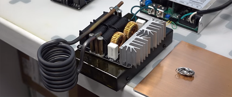
The induction heater is built from a custom Zero Voltage Switching (ZVS) driver and powered by a small 48V, 1000W power supply. While this makes for an exceptionally small induction heater, it’s still very capable. In the video below, it only takes a few seconds to heat a screwdriver up to a temperature that will melt solder.
While an induction heating machine is essentially useless for irons unless you have a few antique, unpowered, blowtorch-powered soldering irons, it does make for a great solder pot. [Proto G] replaced the working coil in his induction heater with litz wire. The actual solder pot is made out of steel conduit wrapped with aerogel-infused fiberglass insulation. Compared to his old solder pot, this machine heats up instantly, and is more than capable of wetting a few wire connections.
The future plan for this inductive heater is to make a few more attachments for different metals, and a [Proto G] has a few aerogel blankets he could use to make some small metal castings.


“:[Proto G] built a small, desktop induction heater” – uhm sure looks like an off the shelf inductive heater to me: http://www.aliexpress.com/item/1000W-Low-ZVS-High-Frequency-Induction-Heating-Board-Modul-Coil-Machine-20A/32454893604.html?spm=2114.01020208.3.10.ZZtuDn&ws_ab_test=searchweb201556_9_71_72_73_74_75,searchweb201527_3,searchweb201560_9
Too much credit…
He did say in one of the videos that he was going to design a ZVS but found it easier to just buy both units and plug it all together (he also said he was going to put links to the ones he bought in the notes for the videos but I’ve not seen anything).
When one “builds”, it can cover quite an extreme range so HaD are using ‘built’ in the way people ‘build’ flat-pack furniture rather than meaning they chopped down the trees.
However, to give [Proto G] some credit, he has been building the heating vessels himself.
You beat me to that comment, so I’ll add that that Chinese gadget can be used to drive the primary of a fairly decent Tesla coil. You don’t even have to wind your own secondary: http://www.aliexpress.com/item/free-shipping-tesla-coil-generator-secondary-coil-for-tesla-coil-diameter-110mm-height-50cm/1671816705.html?spm=2114.031010208.3.48.4nqEEC&ws_ab_test=searchweb201556_1_71_72_73_61_74_75,searchweb201527_5,searchweb201560_9
Ugh… Forgot to delete the search string from the URL.
Beats the one I wound in a oatmeal box years ago!
One built from scratch: https://www.youtube.com/watch?v=EzYWmG0faBM
Yeah, using really inefficient coils.
He provides the link to Amazon where he bought the thing, why is this presented as him building it? This is what he linked in the youtube description: http://www.amazon.com/Nihao%C2%AE1000w-Voltage-Induction-Heating-Module/dp/B016CUVD0C
Present it as a crucible build if you like (though that wasn’t explained very well) but not as an induction heater build.
The point of the youtube series is to show others the many practical uses for inductive heat. I am making all of the attachments myself and explaining how they work. The coils that come with the unit are inefficient and I explained why in the second video.
Can you share the make/model of the power supply?
There’s a link in the video description. I bought mine used on eBay for about $100.
They’re all over eBay coming from China, search “ZVS induction”
What is you level of understading of this board, how difficult would it be to control the out put of it based on temperature, or wattage?
You clearly didn’t watch my other videos or read the video descriptions. The ZVS driver is actually the least expensive part of the whole setup. The 1000W power supply was about $100 used. I’m making/designing the attachments for the heater and explaining how they they’re used.
Another cheaper option is to use four Lead Acid 12V 7Ah Batteries in series. They would probably cost about $80, and you could charge them up at night using a nightsaver rate,.
1000 KW induction heater is very nice!
Hi,
are there some calculations or a sort of minimal rules when you design a new coil??
e.g no of turns vs coil diameter vs wire / litz wire size ??
thanks,
http://s.click.aliexpress.com/e/Fuv7yzvvR 1000W Low ZVS High Frequency Induction Heating Board Module Coil
Those wires between the power supply and the heating board are pretty thin for 20 amps…
Perhaps he intended this to be a combination induction/resistance heater.
It draws 6A at 48V. The “1000W” is pure bullshit or, as they say in the audio marketing biz, it’s instantaneous peak-to-peak power at 99.9% total harmonic distortion.
Nope, it draws 6A with no load. I have ran it up to 23A at 48V. The power supply is pulling 1100 Watts from the 120VAC outlet when a large load is introduced. I have it hooked up to a power meter.
My bad. But if I hadn’t missed that I wouldn’t have come up with my fusion reaction snark and the whole world would’ve been poorer for it. Or not.
Ah, I’ve figured it out! Those two toroids provide magnetic containment for the self-sustaining fusion reaction that enables this thing to put out 1kW with only 288W in. What look like capacitors are actually hydrogen fuel cells. Not bad, but not as efficient as I’d expect. Perhaps these were rejects from the Shanghai maglev train.
It draws a lower current with no load and when he adds a load inside the primary coil (e.g. a screwdriver) then it draws more current.
They’re 14AWG and they are perfectly capable of handling 23amps without heating up. They’re cool to the touch even after running the machine for 10 minutes. The machine will only run for about 1 minutes at a time anyway because the insulation is effectively keeping the solder in a liquid state for up to an hour after the power has been removed.
Why didn’t you show up sooner before we all (well, some of us) made fools of ourselves with ignorant comments? (Says Rod, whilst polishing his mirror.)
Great story but Who changed the pronunciation from solder to souder ?!? it bugs the hell out of me…
I thought all americans call it souder? In Scotland it’s solder
In french it is also souder ;-) Though I thought it was only a french word…
nope, in French ‘souder’ is the verb ‘to solder/weld’, the substance is called ‘soudure’.
I’ve never heard anyone, American or otherwise, say “souder”. I’ve heard “sodder” (US) and “sohlllder” (UK).
I took that as a reflection of how their regional accent pronounces “ou.”
FYI, if you’re going to quote pronunciations in writing, you need to use pronunciation symbols. Your “from solder” presupposes a lot. :-)
Sorry, that’s how everyone I know pronounces it. I have always pronounced it that way.
I have happened to build a couple of powerful ZVS circuits and used some of them for induction heating. The results were cool but not as spectacular as the Author’s. My main problem was the heating in the tank cap (eventually i have used a 2-pound power correction factor capacitor for this, although it’s a brute force method of solving the problem). The circuit itself proved to be nearly indestructible – the solder traces burned well before the MOSFETs died.
I wonder what is the actual frequency and what capacitors have been used for the tank cap?
He said “about 160kHz”.
The capacitors that were used were the ones that came with the pre-made board. :-)
Actually, if you look closely at some of the AliExpress photos, you can see that the capacitors are standard 0.33μF 630V thingies.
You could also use the coil for induction reflow soldering, though perhaps only for sturdy stuff like connectors rather than delicate components that it might fry. I suppose you’d need to Arduinoize the power supply to control the heating profile. Has anyone here tried it? Maybe I’ll use the idea as an excuse to order one of these things. Of course, I’ll also need to buy a Tesla secondary coil as a backup use in case the soldering isn’t practical, and I’m sure I can find a few other things to pad out an AliExpress order…
After watching the second video, I can see that this project was just an excuse for [Proto G] to give a lecture on materials science.
Remember those plaster, baking soda & vinegar volcanoes you made as a kid? You could use one of these induction heaters to make REAL lava! How cool is that?! (Not very, I guess.)
Hey, HaD–If you’d let us edit our comments, I wouldn’t need to keep bloating this page with my stream-of-consciousness rambling.
Okay, time to go hijack someone else’s post…
I’m pretty sure induction has no effect on rocks deprived of metallic substances.
Perhaps one could get away with making a furnace out of a hollow piece of steel, i think however this is an impractival approach.
On the other hand i have seen a video of heating things up by placing them in a microwave in a shaped graphite
block. I wonder what temperatures would this yield.
Metallic container, of course. Do I need to spell out everything? :-)
Did you see the 3rd video in the series? He used a graphite container which got quite toasty.
The graphite container is just to hold the hot contents without damage. It’s the metal inside that gets directly heated.
Hmm… A mixture of granite and iron pellets might work even better… Okay, off goes the AliExpress order!
Scrolling through and accidently flagged Report. Brian, please ignore.
Nope. The graphite is not just for holding the hot contents. Graphite is a great susceptor because of it’s ability to absorb electromagnetic fields and convert them to heat. That’s why it is used in my crisper sleeves in microwavable food.
See here: https://instagram.com/p/9HCYTcvmNB/?taken-by=protog42
I think my pedestal has developed some serious structural flaws.
See the black pipes. They use to be shiny copper looking. Running just water threw the copper pipes is better than nothing. Best case would be to use transformer oil and a close circuit cooling system. Pump radiator and all.
I would reform the coil with longer straight leads. (move away from the PCB) Leave a tail pass the connection points on the PCB. (for the close loop cooler hoses). There is a lot of heat being thrown off the crucible. It must be taken away, or you will suffer the damage. YES, the wire from the PS, is way too small. 12ga at least.
Finally. Graphite crucibles can be found on EBAY real cheap. You can even use furnace potting compound too. And really all this melting should be DONE OUTSIDE. All kinds of nasty gasses are created melting this stuff. Lead come on now. Ever heard of lead poisoning???
Jeez… There’s always That Guy who obsesses the tedious safety stuff. This is antithetical to true hackers, y’know.
I wouldn’t say that was obsessive, the first two points would lead to a much better build with a longer lifetime. Nowt wrong with wanting to build something more effectively.
The comment on wire gauge is more than fair, that wire is shockingly thin for what is passing through it, just look at the PSU terminals!
And I’d second the point of performing melts outside, even if just for the one time you accidentally knock the crucible over for whatever reason.
I wasn’t serious. Just poking fun at the folks who always feel compelled to show off their deep wisdom by adding painfully-obvious safety warnings to any HaD post about something that has the slightest chance of singeing your fingertip. Anyone far enough up on the Darwin scale to matter would know to do this outside.
Why do the Darwin awards exist in the first place. Fortunately the Darwin gene pool is very shallow. I only point out the oblivious because too many people will go out and cook with one these. And kill there family with the fumes. I investigated building one of these. There are many designs available. All are improved by cooling the coil tank circuit. The device being used can be purchased on EBAY ~$50. Build your own is safer, you can select to spread out the cap currents by using many more caps at a smaller value.
Out of all the designs this one is the easiest to beginner build, it involves more parts but is safer in my opinion:
http://kaizerpowerelectronics.dk/general-electronics/royer-induction-heater/
Darwin tip: Don’t just dangle a metal rod in the coil. What do you think will happen if the coil is shorted out? You will standing damn close too.
@[Ron B] (’cause we’re at the bottom of the allowed comment nesting) Gawd, I LOVE your “point out the oblivious[sic]”, and it’s going to be my new snarky catchphrase. Was it intentional, or did you get a visit from Mrs. Malaprop?
Did you see the next two videos? The coil was replaced with litz wire. It more efficiently transfers energy without heating up and I used good enough insulation around the solder pot to keep the heat from transferring to the coils. The 14AWG wire used is just fine for the length of time the machine is used. They are cool to the touch even after running the machine for 10 minutes straight. The machine will only run for about 1 minute at a time anyway because the insulation is effectively keeping the solder in a liquid state for up to an hour after the power has been removed. I will probably replace the 14AWG with litz wires before I build the enclosure, but the wires are just fine for now. I also made an induction graphite crucible attachment in my most recent video. You spoke too soon. The smoke in the video is the flux, not the lead. It does not smoke when using a solder bar, but I ran out so I just added rosin core solder to the pot. Realize the boiling point of lead is about 3180F at standard pressure, so this is hardly giving off lead vapors if any at all. In the second video, I am running the machine hotter than necessary for the demonstration. I wanted to show the multicolor oxidation layers that aren’t as vibrant at lower temperatures. I normally cut the power once it hits 1000 degrees fahrenheit. Not hot enough for lead vapor to exist.
Desktop? Can it be scaled down to keep my beverages warm?
Doh! I mean can the output be adjusted to lower output…
It was all tongue in cheek anyway…
No, you had a great idea. Instant Turkish coffee!
Was about to order one of these, but then did some more careful reading. With a 48V power supply, the current draw is only 6A. So, “1000W” is pure marketing BS (not that I REALLY believed that the little switcher was actually delivering 1kW). Also, there are some sobering cautions for making it work without self destructing. See the comprehensive details in this guy’s listing: http://www.aliexpress.com/item/1000W-Low-ZVS-High-Frequency-Induction-Heating-Board-Modul-Coil-Machine-20A/32454893604.html
Not marketing BS….It can do 1000W but you have to increase the voltage. As he states, 53V @ 20A is doable and equal to 1000W, but the caps will probably heat up. This is running on the edge, but I think it could be easily done for short periods of time or continuous if the coil was water cooled and some type of cooling was added to the caps.
I’ve built ZVS drivers myself nearly identical to this. It’s almost always the resonant caps that heat up and fail. The transistors should be fine because ZVS (Zero Volt Switching) is awesome and causes nearly no heating in the transistors.
You’re right–I was too quick to judge. Then, our friend [Proto G] really is asking for trouble with his wiring.
Okay, placing my order now…
They’re 14AWG and they are perfectly capable of handling 23amps without heating up for the amount of time they’ll be used. They’re cool to the touch even after running the machine for 10 minutes. The machine will only run for about 1 minute at a time anyway because the insulation is effectively keeping the solder in a liquid state for up to an hour after the power has been removed. I will probably add different wires before I build the enclosure, but the wires are just fine for now.
That is apparently only under conditions of no load.
Ibid. I screwed up.
on ebay they say it is a voice changer item 311454897559
It would probably change your voice if you put your fingers across the output terminals.
Half baked idea here… has anyone ever tried reflowing a circuit board using an induction heater?
Only reason solder melted was due to the container.
A lot of electronics don’t like being in a strong EM field.
Would take a lot of energy.
That’s not true. It will melt solder wrapped around a copper tube. Materials with a low resistivity will still heat up, it just takes longer.
Induction reflow is sometimes used when soldering metal parts, including connectors, so I have some doubt about [RandyKC]’s assertion that “Only reason solder melted was due to the container”. Also, the screwdriver that [Proto G] inserted into his coil certainly got hot, so I don’t see why the same thing wouldn’t apply to solder (hey [Proto G], stick a piece of solder into it and end this debate). However, I suspect that the induced currents and heating would be fatal for lots of more sensitive components ([Proto G], ditto). Without careful control (which is perhaps impossible anyway), this is going to very quickly take some things far above soldering temperature.
It will melt solder wrapped around a copper tube. Materials with a low resistivity will still heat up, it just takes longer.
I wonder if one or two MOT rewound to 40 – 48V secondary would be suitable for a power supply. Rectified, smoothed etc…
Bah! What kind of hack is THAT?! Since the induction gadget is tolerant of a wide range of voltages, just use a saltwater variac, a big honkin’ bridge rectifier, and a saltwater capacitor for filtering. There’s probably some way to homebrew a rectifier (using saltwater?), but I can’t think of it at the moment.
have you seen old saltwater resistive dimmers? they used to use them in theaters, basically steel rods in a triangle or inverted v, with the resistance increasing as you lift it out of the water.
You could, but I wouldn’t. The power supply is regulated and adjustable with current sensing fans. It also has constant current limiting and recovers automatically after a fault condition is removed. Overload protection is pretty important when working at such high power.
Here’s what I’d like to know- and full disclosure, I don’t know electronics that much. Please, can you overlook that?
I do know what I’ve seen large ones of these induction heaters do, though- melt steel.
How practical would this sized model do, given a good graphite crucible, in actually melting real metals?
Does it have enough power to do this? I’m guessing that would be reflected in it’s amperage somehow?
Say small amounts- like a sample of metals the size of 1/2 a film container. Going again, with this very
rudimentary understanding, would that volume of aluminum be meltable? Iron? Steel? Precious metals,
such as gold, or platinum?
There are only maybe 3-5 items that I would absolutely learn whatever electronics needed to make.
At the top of that list is a micro induction furnace capable of melting precious metals, or even exotic ones.
I do a lot of prototype work on small parts that I’d like to be able to cast first with no torches, in exotic metals.
Would this fit the bill, or if not, could it, if power supply/water cooling was upgraded? Thoughts?
Look at my latest video. I melted aluminum with it. I haven’t tested any other metals yet but it will exceed temperatures of 1000C so there are plenty of materials that it could melt.
Here’s a link to the induction crucible: https://www.youtube.com/watch?v=_9ZK_Hs99FU
Hey, slight question. In these induction heat thingies, what determines if the alimunium gets levitated or not, like in this video: https://www.youtube.com/watch?v=VydPQuLyEns
The reason it’s levitating is because he reversed the direction of the coil near the top so you end up with two different magnetic fields. This causes the aluminum to levitate. I will be trying to recreate this in a future video. I would be curious to see how a magnet would react in a reversed coil like that.
steel has a higher resistance than aluminum, at least i’m pretty sure, so it should melt sooner. it also doesn’t conduct heat away as well, so you should be able to melt steel. be very careful with galvanized metals, as the thing that makes them galvanized is zinc, which can cause metal fume fever and is very poisonous as a vapor.
You may note that Proto G melted aluminum, but not very quickly, and not very much.
The energy lost to the environment per second is proportional to the difference in temperature between the melt and the environment. What this means in practical terms is that the energy lost to the environment goes up exponentially with temperature, so for a given power input the temperature will rise until the exponential loss equals the power input.
But also there’s the R-factor of the conduction path from the melt to the environment to consider. You can increase the R-factor, reducing the rate that energy is lost, by insulating the crucible and using a lid. A good flux will also help.
So to make a practical melting pot with 1000 watts you should bury it inside firebricks and use a crucible with a lid. Firebricks are cheap, available at the hardware store, and easy to work with. They’re like hardened styrofoam, and can be cut and worked with woodworking tools.
Consider this as a starting point:
http://www.instructables.com/id/Homemade-Electric-Kiln/
But if you’re going to do that, it would be simpler to just get some Kanthal coils or scavenge some coils from a junked oven (and the temperature set dial). The wiring for a traditional “oven” kiln is simple, and doesn’t require the $50 induction heater or $100 (used) power supply.
Then you could bury the coils in the walls of the kiln, and could heat anything that would fit in the kiln chamber.
Just a suggestion, mind. Playing with induction heaters is also neat.
As others have said, he melted aluminum. It’s one of the worst metals to melt in induction, as it’s resistivity is so low it’s like running an open coil (high voltage, low current), which is inefficient. You’ll find that the precious metals are similar, so I think it’ll melt fine. Copper is even worse. Steel is ideal and the primary target of induction heating and melting in the world. titanium oxidizes instantly without a hard vaccuum or a pure argon environment.
The physics of melting doesn’t change, and other than heat losses, the power density stays similar, so you can somewhat rule of thumb how much you can do based upon similar sizes. For instance, there’s one unit online that has a peak power of 2.8KW and can melt 1KG of gold, so in theory you could do 300g of gold in this if everything was running peak. That would require careful coil design (see next) and water cooling (open or closed loop, DI water).
http://ultraflexpower.com/products/easymelt/
There is one has both a high turn optimized coil (higher turns = higher voltage = more induced current in the material) and is designed to be tight to the crucible, minimizing air gap and maximizing efficiency (coupling of the field to the target material).
I really do recommend hitting a local library, or even better a university library, and seeing if they have any books on induction heating. Newer books will get into control systems, simulation, numerical design, etc. Older books will be more practical. Things won’t be as optimized, but you’re looking for a melter, not a heat treating application.
Ok, now that these are easily available, how do we add temperature or wattage control that is more that just on/off.
I²R is how this works.. at least in the load.
There are devices for loosening “frozen” nuts, bolts and O2 sensors on cars, They come with an assortment of preformed rigid coils and litz wire for forming in place where you can’t use the rigid coil. They are sold under names like Bolt Buster and MiniDuctor. They are rated at 1000 Watts, They are in the form of a hand held cylinder (pretty small),usually run on 120 VAC though also available for 12 volt battery operation, They go for $500-$600. They are not water cooled. I wonder whether one of those $40 Chinese ZVS ‘s on E Bay will do the job. The power supply probably does not have to be self contained, like theirs. Also, there seem to be a number of variants on E Bay, with and without fan cooling. Has anybody checked out the different models? All the Chinese ones come with a warning about switching power supplies. They start slow and if connected to the ZVS before the voltage reaches 12 volts, you blow the MOSFET’s I don’t want to reinvent the wheel. If anybody has had any luck building a DIY Bolt Buster, using one of those E Bay ZVS’s I would appreciate any info. Thanks.
So my 12 year old wanted to try this out, so we got almost exactly the same items in the video, but with weird results. The board seems to pulls just over 25A and causes issues for the power supply. We put a massive resistor on it and now the power supply goes to about 36v and still ~25A. So the resistor gets super hot, the board gets really toasty, yet refuses to heat anything up in the coil. We contacted the seller of the driver and they agreed something must be wrong since it’s marketed for 20A. The sent a second board, but behaves exactly the same way. Anyone seen this before?
Just a guess, but are your heatsinks shorted together in some way? Each heatsink is connected to the thermal pad on the back of its respective MOSFET (which in turn is connected to that FET’s drain, at least on he IRFP260N), so unless the maker of your board placed silicone pads between your heatsinks and FETs, connecting the two heatsinks would short your supply voltage to GND through at least one of them. Hope that helps
Also, make sure to power your power supply a few seconds before connecting the zvs
I am from pakistan.Is that possible that you sell me this induction heating device of 1000 watts so that i do not have to make it. you can tell me the cost for this device. i will pay for it.
just a reminder. plzz answer me. im waiting for ur reply. can you sell this device to me?
I use 12V,20A 240W power supply and Transistor fins very hot ,but I use 1.5mm metal is not hot
I don’t know why…
We went through 3-4 of these board to get one that finally worked, due to the poor build quality, sometimes the board would get super hot, various components, and the material wouldn’t at all.
still i am waiting for zvs 1000 watts 12volts for small melting furness if you have pls reply me
You can order them on Amazon, that’s where we found ours.
can you connect 2 of these in parallel to make a 2000 watt unit ?
I doubt it. Each board has it’s own Mosfet switching system. I don’t think you could rely on them both switching at the same time. if they don’t switch at the same time. I am pretty sure the Mosfets will fail.
See:
http://spaco.org/Blacksmithing/ZVSInductionHeater/1000WattZVSInductionHeaterNotes.htm
Well, it’s 2 years later. In answer to the question:
Can you connect two of these in parallel?
Well, yes you can,- sorta.
They now double or triple the number of Mosfet pairs so you can get 1800 watts or even 2500 watts out of one board. Of course you will need a bigger power supply.
See:
https://spaco.org/Blacksmithing/ZVSInductionHeater/ZVS1800Watt/1800-2500WattZVSInductionHeaterNotes.htm