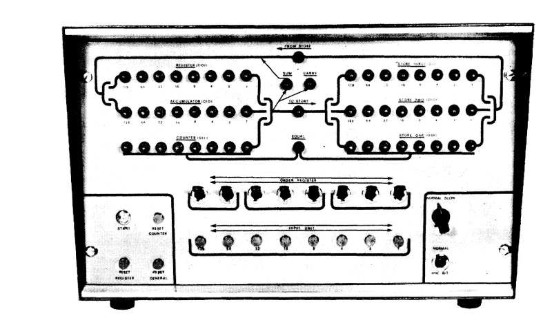
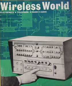
What kind of computer could you build in 1967? Well, if you were reading Wireless World (a UK magazine) and had a good bit of spare cash, you could build [Brian Crank’s] Wireless World Computer. You only needed 400 germanium transistors, 1800 resistors, and an odd number of capacitors, switches, diodes, and neon bulbs. You also needed a good bit of patience, we suspect.
In 1967, the computer cost about 50 pounds to build (perhaps $125 at 1967 exchange rates which would now be about $900 in today’s money). To save parts (and thus money and build complexity), the computer used a trick: it processed data one bit at a time. Many older computers did this, including another UK computer named EDSAC.
In fact, we couldn’t help but wonder if [Brian] had some knowledge of EDSAC as the machine has some superficial similarities (for example, instructions are called orders). The author admits the logic is not always minimized, but says he elected to leave it maximized to help illustrate the machine’s operation. There were several basic logic circuits built from transistors, including inverters, NOR, and AND gates as well as various flip flops and a comparator. The computer’s main logic was described in terms of these building blocks.
![EDSAC I [Photo by Computer Laboratory University Cambridge CC-BY 2.0]](https://hackaday.com/wp-content/uploads/2015/10/edsac_12.jpg?w=400)
We assume [Brian] used germanium transistors because they were cheaper than the relatively new (and much better) silicon variety (and the inferior devices were probably being dumped as cheap surplus by 1967). Apparently several schools built one of these computers. It was more capable (and probably more expensive) than its contemporary paperclip computer (although, in fairness, that one did have a program drum).
Thanks to [EdS] for pointing this one out to us.


Nice writeup! Maybe someone who met one of these machines can tell us about their experience: Alan Wilkinson then at Spennymoor Grammar originated the design ideas, I think, which were picked up by Brian Crank, and slightly later Hector Parr at Darlington Grammar and then Barnard Castle School built first DENICE and then the BRENDA computer. Both Alan and Hector have published books about their work. See the discussion at http://forum.6502.org/viewtopic.php?p=22872#p22872 which includes a simulator for BRENDA.
I assume this design could be replicated using 7400 TTL chips? How about in an FPGA?
Well it logic so It could be done with 74xx TTL. I would probably fit into a CPLD. FPGA’s are much larger.
you can easily fit this in a mid-size CPLD
Tubes and ping-pong balls?
But could you do it with tubes?
relays?
Napier bones?
Paper Clips?
I have box with approximately 600-700 pieces of unused germanium switching transistors. Now I need nothing more than a few months of vacation.
Those transistors on ebay are probably worth more than a modern day computer.
+1
Those transistors do have special place in my junkbox – and in my heart ;-) As well as lot of other items, like “globe bottle” 4-pin triodes, heaps of other vacuum tubes and nixies, or old 8-bit CPUs and EEPROMs, I’m not going to sell it soon – though I admit I already sold a lot of “junk” and left only the most valuable pieces. Moving my workshop from 30 square meters to 10 square meters was painful.
Well,
It’s now 10 years later! How did you fare?
regards
G7VFY
Far better to make a computer than to make some cash.
If you haven’t used it for 40+ years, chances are that it won’t be used anyways.
Well, I’m only 31, owning them for a few years and hoping to live for a few decades more. Once I’ll feel like there is nothing to do with them anymore, I’ll probably sell it. Long live ebay! ;-)
What is their part number?
RÖB,
some of my old transistor don’t have numbers, just colored dots like capacitors used to have….
B^)
I’ve got a couple of parts drawers full of transistors with date codes ranging from 1962 to 1964 in a package type that I’ve never seen anywhere else. Given the age, they’re probably germanium, but I haven’t tested them to find out. They’re in drawers labelled “vintage transistors”, and I am saving them for a special project that needs a bit of retro flair. I just haven’t come up with such a project yet.
I wonder if I have enough of them to build one of these computers?
Might be that they’re too accurate to replace valves in audio work, not accurate enough to replace silicon in digital work. Apart from being unreliable and delicate, what were germaniums famous for?
I would guess the computer would work just as well with silicon, surely the transistors are going to be in saturation, or fully off, most of the time?
Might be more useful for building 600-700 “fuzz face” guitar pedals instead of one computer.
Not all transistors sound right apparently… so sure you might get a hundred good ones out of that unless they’ve already been picked over.
Sort of like reeds for woodwind instruments?
Q: How many clarinet players does it take to change a lightbulb?
Answer: One, but they’ll use a hundred bulbs before they find one that works for them.
Less like reeds and more like matched pairs or triplets. In some cases you want matched response curves, as close to identical as possible. Other times you want exact inverses. “Close enough” was what got sold commercially, but the pros had someone tune them.
I’m having a REAL hard time reading those schematics with V- higher on the page then 0 Volts or V+
It’s amazing how much electrical engineering is just pattern matching for me I guess.
The way it is flipped actually makes it easier to understand. I just have to pretend that they are NPN transistors and invert the polarity.
This is just a discrete DTL ALU. It doesn’t even have a program/data store, branch unit etc. :P
I was wondering what it could do without program storage. An ALU would be more like it, plus a couple of registers. An ALU alone is not a computer!
Yes but here is the trick. You could add a program store pretty easily. Same problem with 8 bit micros that appeared soon afterwards. Great chips but they still needed a program store.
How many peole today understand micro code rather than assembly code? That is what this machine was about. Okay so you pressed the button and eight clocks later you had processed eight bitss. It did not matter that dtl was not going to win any races. With a simple program store i could key in in decimal say 31 then 5 hit the multiply button and up popped the result on a seven segment display. All before we had calculators.
Isn’t a lot of old Russian tech like that? Or was it that they used V- and 0 instead of V+ and 0 like us Yanks and Brits like so much?
ECL circuits are usually that way too with Gnd and -5.2V. In ECL, the “Gnd” or the more positive rail is the reference rail where all the logic levels are defined against.
I always thought the Kenbak-1 was the first PC, guess I’m wrong
First personal computer? I recommend the quiz at
http://www.blinkenlights.com/pc.shtml
funny thing is that I took that quiz ages ago! Still thought the Kenbak was a better contender!
The Kenbak actually was a computer, this isn’t. At best it’s maybe a logic trainer. I can’t think what practical use it would have, without having to add the missing parts to make it up into a computer. Nobody needs a manually-operated binary ALU.
I remember this article! I think we built some of the logic gates at school, with switches and lights on breadboards. I also bought stuff mail order from LST Components. I would have been 16 at the time. Great blast from the past.
I love discreet transistor builds. Always reminds me of college project we did. It was a software class and I don’t remember how we convinced the professor to let us build this. 216 transistors, and all it could do was add.
Also, we (I) picked the wrong value resistor for all the gates. At 5A standby current, it was probably the most powerful adder in the world. Unfortunately the school doesn’t have the project pages up any more.
http://imgur.com/PRqDg3P
I blame the soldering fumes from projects like this one for my current dementia.
Sure wish we could edit our comments, because what I really want to say is:
Thanks to projects like this, I’m mad as a hatter.
What about the voltage dementia?
Does that have something to do with potassium channels?
Not sure if I did any of these.
My first logic was built with 2N404’S, etc back in the early 60’s – I had found some surplus boards that were built with them, and copied the logic for JK flip flops and gates that were on the boards.
But the only question that matters is: will it run Windows 10?
I actually scanned and uploaded that manual ! I actually used a similar computer at school in 1972 which had been built by the Music Teacher Hector Parr. Hector went on to build another version at his next school. He can be seen here with what looks like an SWTP CT68 in 1978.
http://dre.durham.gov.uk/pgDre.aspx?&SEARCH=&TERM=&ID=DRE10345&PIC=Y
and if any one wants to read his book its here:-
http://www.lulu.com/shop/hector-c-parr/music-maths-and-machines/paperback/product-1021349.html
actually the Manchester Baby or SSEM from 1948 which pre-dates EDSAC was also a serial machine. There is a replica at the Museum of Science and Industry in Manchester….
I afraid to say I built the ww computer along with a program store and some bcd to decimal displays hooked onto one of the registers. Plus a separate control console.
I must have been about 16 still at school. It was all boxed up in a few really nice painted boxes. A friend of mines father worked at ICL and provided loads of boards with discrete parts on them. The parts were all removed and fitted to hand made pcbs. Painted etched and then drilled and drilled and drilled.
The end result was a nice console which you entered numbers on pressed add subtract multiply and divide. It then converted the numbers to binary did the calculation and converted it back to decimal.
Took me an entire school summer holiday to build.
The following year it was on display at the school open day.
I have no pictures and no circuits apart from an original manual I think produced by ww.
Brilliant!
I have a copy of Electronic Computers (Pelican) By S. H. Hollingdale, G.C. Tootill from the same year, surprisingly there are still a few copies available on ebay for a modest price. It is +300 pages, I wonder if I should scan it?
Whoa, single-bit processing… So, what’re we at, now…? 64bits and 8 cores? What if we had a 512-core single-bit processor… hmm….
I came across this page by accident. My name is Brian Crank and I designed the WW computer – I was on the WW staff at the time. It had nothing to do with EDSAC – it was designed it from scratch to teach myself something about computers. It used germanium transistors because I discovered a source of reject devices (a company called LST components) – I could not of afforded ‘new’ devices.
My next major project was called the WW Logic Display Aid which did not get as much publicity as the computer but was a much more significant device.
Much later (1975) I built an Altair 8800b computer from MITs – it gave many years of service and ended up with both Floppy and Winchester discs
Excellent to see you here Brian! There’s a conversation over here about your WW computer:
http://forum.6502.org/viewtopic.php?f=3&t=2333
Hi ‘Ed S’
The WW Computer was built at my home. In the beginning I made an 8-bit shift register on a strip of ‘Veroboard’ using selected reject transistors and made it work. I found I could indicate the state of each stage of the register with neon lamps driven by a transistor driver. The various bits of the machine were constructed on more Veroboard sheets which were all screwed to a large sheet of wood! Eventually it all worked and I told Wireless World about it (I had originally joined the magazine to help the Editor in chief, Walter Cocking, to develop a colour TV for home construction.but I was now on the editorial staff). WW expressed interest so I designed a ‘posh’ front panel and fitted the rest of it into the box. Behind the panel it looked like a birds nest.
To make sure, WW invited an engineer from ICL to give an opinion. He was very much in favour so I wrote the articles and it was published. A great deal of interest was generated so it was decided to publish the series as a booklet. I think several schools made it.
If you are interested I made a brief cine film of the project when it was mounted on the wooden breadboard. The film has been digitised but is a bit out of focus. It shows the thing working with flashing lights. I’ll send it to you if you are interested.
As I said my best design was the WW Logic Display Aid: http://fano.co.uk/history/BlockDiagram.zip which attracted the interest of the British Computer Society.
Kind regards,
Brian
It would be great to see the film Brian – could you upload it to YouTube, or give me permission to? There’s a number of people – a small number – who really delight in this kind of history. (If not YouTube, there are many other ways to share videos online.) You can send me a private message using the button under my photo here: https://hackaday.io/BigEd
Hi,
Further to our previous emails I have located the original 8mm film and have mad a copy that you can access HERE;
https://drive.google.com/open?id=0B_xyANVKU4qIZkpKTmdUczR1eEU . The quality is much better than the previous clip.
Best wishes,
Brian
Thanks for the improved video!
Hi Brian,
The neon drivers were rather clever. If I remember the transistors were silicon? But could not switch the neons directly just alter the bias enough to cause them to go from an ionized state to an off state. The transistors had a limite vce. Leds would have been great.
The ww colour tv was something i built during another school holiday. The broadcast test card was mixed with test adverts during the afternoons I worked on it. Oh for some test gear to work with.
Thanks for the interest Geoffrey, It was a verylong time ago The neon drivers were 2S301 silicon transistors and there was 66 of them! That means the computer had 468 transistors in total (there were two power devices). I made the machine in our front room, I didn’t have a workshop, and wife never managed to remove all of the blobs of solder from the carpet! Leds would have been great indeed!
Brian
Ps I have a cine film of the device before it was put in a cabinet, as mentioned in an earlier post. I intend to have it professionally digiised and will make it available after it’s done.
Excellent film. Is that a programming plug board on the right?
Sorry Geoffrey, just come across your reply. Yes, it was a plug board and I had plans for using them as some kind of program store but it would have worked out too expensive. I even toyed with the idea of making a plug board using dress making press studs but never did – it probably would have worked!