[Alex Lao] has been playing around with the CPLD-like parts of a PSoC. Which is to say, he’s been implementing simple logic functions “in hardware” in software. And after getting started with the chip by getting accustomed to the different clock sources, he built a simple AM radio that transmits at 24 MHz.
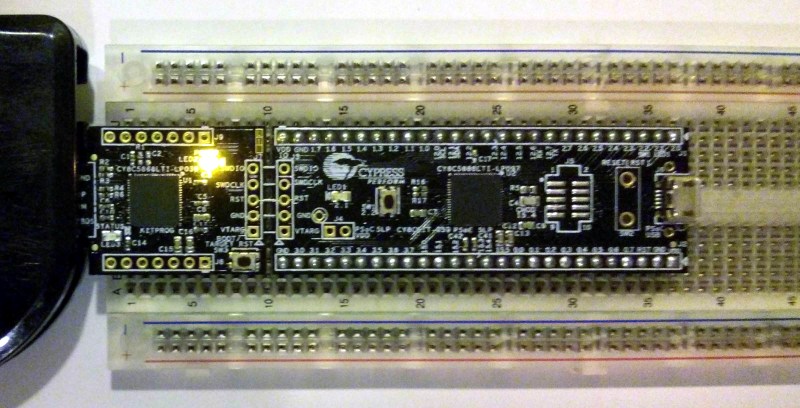
The device that [Alex] is learning on is a Cypress PSoC 5LP, or more specifically their (cheap) prototyping kit for the part. The chip itself is an ARM microprocessor core with a CPLD and some analog tidbits onboard to make interfacing the micro with the outside world a lot easier. [Alex] doesn’t even mess around with the microprocessor, he’s interested in learning the CPLD side of things.
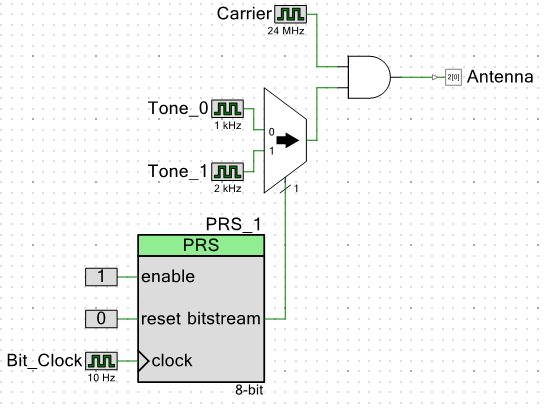 He starts off with a 24 MHz carrier and a 1 kHz tone signal, and combines them with a logical AND function. When the tone is on, the carrier plays through; that’s AM radio at its most elemental. Everything is logic (square waves) so it’s a messy radio signal, but it’ll get the job done.
Adding a multiplexer up front allows [Alex] to play two tones over his “radio” station. Not bad for some simple logic, and a fantastic Hello World project for a CPLD. We can’t wait to see what [Alex] is up to next!
If you’re interested in getting your feet wet with either CPLDs in general or a CPLD + micro system like Cypress’s, the development kit that [Alex] is using looks like a cheap and painless way to start. (Relatively speaking — PSoCs are a step or two up a steep learning curve from the simpler 8-bit micros or an Arduino.) Hackaday’s own [Bil Herd] has a video on getting started with another member of the Cypres PSoC family, so you should also check that out.


I don’t know if I would call these PSoCs, “CPLD” like. They have some programmable logic but it’s very small even compared to a CPLD and it is also just one of many parts of this chip. Also these PSoCs have programmable analog circuits. CPLDs and FPGAs don’t have any analog.
Worth a mention is that these cheap PSoC 5 boards have a JTAG programmer instead of the usual USB-Serial bridge. It can be broken off and used to program the earlier 4100 and 4200 boards.
I should mention Cypress refers to the PSoC’s digital logic resources as “Universal Digital Blocks”. It contains a programmable data path that can be used to lower the usage of the rest of the more generic logic resources.
In any case the distinction between CPLD and FPGA is mostly architectural (FPGAs usually being bigger due to their design being more scalable though). The resources within the PSoC is definitely quite close to the architecture of a CPLD with some hardened logic blocks. I guess some of the older acronyms that point to various programmable logic devices do infer an idea of size so it does get confusing.
To me, the fact that the PSoC contains configurable analog resources has nothing to do with calling just the digital section a CPLD or not since it really has nothing much to do with that. I think it is fair to say it is a system on a chip as the name PSoC implies.
.
Cypress calls the detachable programmer a KitProg and I believe it has the ability to do USB-I2C as well. I have not tested that feature though.
Thanks for reading and thanks for the input!
Fair enough!
I didn’t really want to say PSoC, because you’re hardly using the “system” at all, just the programmable-logic part — the part that’s most FPGA/CPLD like. :)
Still, I’m excited to see what your next steps are. There aren’t that many PSoC resources out there other than Cypress’s own, so it’s nice to see you working through it all. I’m going to buy one of those sticks to play around with, and I’m sure you’ve inspired a few more folks. So thanks, and keep it up!
Really? The higher end PSoCs have up to 20 digital blocks, each of which is a pair of PLDs, an ALU, and datapath unit. That seems pretty substantial next to most CPLDs I’m familiar with.
What’s higher end to you? I have only worked with the PSoC 4 4100 and 4200 and in any case CPLDs/FPGA still don’t have *any* analog.
The PSoC 5 range all have 20+ UDBs, while the 4s are restricted to just 4, which I agree is smaller than most CPLDs.
As for analog, I thought the question was whether a PSoC has the capabilities of a CPLD, not vice-versa?
Each of those PLDs has 12 inputs, 8 product terms, and 4 macrocell
outputs. That’s tiny – each PLD is smaller than one of the original 80s era PALs. I guess it must be enough for their intended purpose of implementing simple state machines, but it seems incredibly restrictive. Even though you have 12 inputs, you can only match 8 combinations of inputs total. (Basically, there’s 8 AND gates on the inputs, each of which outputs a 1 when the inputs matches a programmed pattern of 1s, 0s and don’t-cares, and each macrocell can OR together any combination of those 8 shared AND gates you like. There’s also an optional flip-flop and some carry chain logic between the OR gate and the output.)
Each one is small, yes – but there’s 48 of them in a top-end PSoC 5, as well as 24 datapath modules that are effectively programmable ALUs.
“That’s AM radio at its most elemental.”
That has a name: OOK (On/Off Keying)
I wouldn’t name this OOK. If you look at the block diagram, you can clearly see that he is either using 1 khz or 2 khz modulation, not turning the carrier on or off
That would probably make it FSK (frequency shift keying)
He’s ANDing it, not XORing it or using a multiplier, so it’s OOK.
That symbols is an AND gate and not a summer so the carrier is being turned on and off at either 1kHz or 2kHz.
I just read the HAD write up, and didn’t visit the site.
We used to call this “CW” but now it seems that CW is used for continuous wave. Many many years before CW we had OOK OOK :p
I really don’t want to be a spoilsport, BUT the radio spectrum is extremely valuable & use of frequencies VERY tightly defined, with penalties for illegal transmitters. If you want to broadcast with DIY gear then perhaps get a ham licence & settle on defined bands ! ZL2APS
I do mention that at the top of the article on my site. It is something to be noted here as well.
Since what I am doing here is no different from if you were just using the kit normally and happen to route the higher speed signals to the output pins I would say it is OK.
No one should attach this to an amplifier or even an antenna. This is a quick weekend hack and not much else. I did walk around with my RTL-SDR with the transmitter running for a bit and I can’t even demodulate the signal coming from the board more then about 3-5 meters away.
All it takes is for some spoilsport to connect 3 m of wire to the output. And careless people will do just that.
I was about to say this. This thing will spew crap all over the bands, just like all other of these square wave AM/FM modulation projects we’ve been seeing lately.
It may be fine for a quick test, but I fear people may start using things like these en masse. That’s bad for commercial and ham operators alike..
“This thing will spew crap all over the bands”
So then it’s just like the Internet?
Why don’t the HAM operators use Facebook like everyone else?
It reaches worldwide and you never know what friends you find?
Because Facebook is littered with clueless losers.
How would you know?
How is Facebook in any way like amateur radio? And I know a great many hams who do use it. Perhaps you should look into the amazing hobby that is amateur radio. You might just find out that it’s a heck of a lot more fun and interesting than Facebook ever can be.
I can’t get Facebook in the middle of the Imbil State Forest.
Amateur radio works fine however.
What he was doing here was just enough for a proof of concept. I thought it would be enough to get a signal to the next breadboard lol but apparently it would go 3 meters or so.
This isn’t a modulator in any way it’s in interrupted carrier and even the term carrier is used loosely as a carrier is normally a single frequency sine wave. In this case the carrier has a fundamental frequency and lots of strong odd harmonics the first of which would be 72 MHz.
I wouldn’t be worried that people will use this sort of thing as it’s very inefficient, at least one third most of the power is wasted.
Had I just used the PSoC to generate some clocks or fast signals being routed to other circuitry the amount of interference generated would probably be much greater then what I got with just the board sitting in the breadboard.
I was wondering about the FCC regulations on development kits when playing with this and I guess they get past the testing because it is not really a final product and is considered a sub-assembly.
Low pass filters, people! Filter that cruddy output.
It most likely qualifies as a Part 15 device, so no license necessary, as long as you use it in the AM band.
He’s not in the AM broadcast band, not even close.
yeah – the “Build an AM radio” is a bit misleading there. It has AM modulation but is not anywhere near the AM Band. I think the 24MHz range is marine radio or emergency services here – will go so – it’s between bands.
Similar, but using a PIC: http://www.youtube.com/watch?v=qIAEdGA_sFw
Harmonics makes it usefull up to 200MHz!
Awesome demo.
I’m surprised that you got reception on higher frequencies 20m away. Were you bandpass filtering _for_ the higher harmonics, or was that unfiltered?
As he mentionned in the comment he only connected a length of wire to the digital pin, radiating all the harmonics.
Filtering an harmonic would not improve transmission power, hence the range.
The base frequency is 1Mhz and he can receive harmonic at 145Mhz at 20 meter range! As one can see this is really a dirty transmitter.
Thats pretty cool!
This thing still takes the cake though:
http://hackaday.com/2012/01/26/sprite_tms-three-component-fm-transmitter/
You can actually even amplitude modulate the carrier using one of the internal IDACs and a pin set to open collector output. A friend of mine has one such project, transmitting audio (read from the ADC) in the AM frequency band, it’s published in the Cypress PSoC4 forum.
It’s a good challenge to try do imaginative use of the hardware. I have implemented a “fully analog output” triangular wave generator, within certain frequency and amplitude limits, using only the hw (and one external capacitor; IDACs pumping current in and out of the capacitor).
I think even the more modest PSoC4 in the hands of skilled hackers have a lot of juice to give.
Doesn’t the digital block have an XOR? I would modulate with an XOR.