Although GRC (the GNU Radio Companion) uses the word radio, it is really a graphical tool for building DSP applications. In the last post, I showed you how you could experiment with it just by using a sound card (or even less). However, who can resist the lure of building an actual radio by dragging blocks around on a computer screen?
For this post and the accompanying video, I used an SDRPlay. This little black box has an antenna jack on one end and a USB port on the other. You can ask it to give you data about a certain area of the RF spectrum and it will send complex (IQ) data out in a form that GRC (or other DSP tools) can process.
The SDRPlay is a great deal (about $150) but if you don’t want to invest in one there are other options. Some are about the same price (like the HackRF or AirSpy) and have different features. However, you can also use cheap TV dongles, with some limitations. The repurposed dongles are not as sensitive and won’t work at lower frequencies without some external help. On the other hand, they are dirt cheap, so you can overlook a few little wrinkles. You just can’t expect the performance you’ll get out of a more expensive SDR box. Some people add amplifiers and converters to overcome these problems, but at some point it would be more cost effective to just spring for a more expensive converter.
Traditional Radio Architecture
![[Billy Cheung's] matchbox crystal radio which we covered in September](https://hackaday.com/wp-content/uploads/2015/10/crystal-radio-matchbox.jpg?w=400)
AM radios carry modulation (that is, sound, in this case) by varying the amplitude of the carrier wave. A diode can recover that varying amplitude and a crystal radio might use a germanium diode, a galena crystal (hence the name), or even a razor blade and a safety pin. The signal won’t be very strong, but high impedance headphones will work, or you could build a simple audio amplifier.
There are lots of ways to improve the simple crystal radio, but they all have similar goals: boost signal strength, or improve rejection of unwanted signals (or both). For example, the Tuned Radio Frequency (TRF) radio used tuned amplifiers before the diode detector to selectively strengthen the signal you wanted to hear.
Superheterodynes
The problem with the TRF is you have to tune each stage to the frequency you want. That problem is what led to the development of the most common receiver type: the superheterodyne. In this scheme, the input signal may be selected and amplified but then it is mixed with a local oscillator. The mixer will add (and subtract) the local oscillator frequency from the signal.
Suppose the input to our radio has two signals: one at 7050 kHz (the one we want to hear) and another at 7200 kHz. Further suppose that the local oscillator is set for 6050 kHz. After mixing you’ll have signals at 1000 kHz, 1950 kHz, 13100 kHz, and 13250 kHz. Why is this important? Because we can now build highly tuned amplifiers that amplify signals at 1000 kHz (known as the intermediate frequency or IF) and reject other signals.
The advantage is that those tuned amplifiers don’t have to be adjusted. That means they are simpler to operate and simpler to make very efficient. For example, good radios might use a crystal filter to reject all the extra frequencies. For a conventional radio, that’s the best way to create practical filters. After demodulation, the radio probably amplifies the audio signal to drive speakers or headphones.
To recap, the basic layout is RF front end, mixer and local oscillator, IF amplifiers and filters, demodulation, and, finally, audio amplification. Remember this, because many of these same pieces will show up in one form or another in a software defined radio.
Using software defined radio, you generally have the same goals, but you don’t quite accomplish them in the same way. The IQ data comes in and represents the entire signal available. In some cases, you have to shift the frequency in the same way you would use a mixer in an analog radio. For the SDRPlay, though, the signal already comes in at zero frequency. There are many ways to filter using GRC, so it is easy to cut off the frequencies you don’t care about (and some filters can translate frequency, too, if you need that).
Sampling Rates
One thing that is paramount with a software defined radio is the sampling rate. If you want a bandwidth of, say, 1 MHz, you need to sample at 2 MHz (at least). However, when you try to do complex processing or even just want to go to audio frequencies, you’ll want to cut down to much narrower frequency band and sample rate.
The GRC blocks use two DSP terms for moving sample rates around: decimation and interpolation. Decimating a signal by 4 will essentially divide the sample rate by 4. Interpolating by 2 will double the apparent sample rate. You’ll often use both to get some non integer change in sample rate. For example to go from 1000 kHz to 44.1 kHz, you can’t just divide by an integer. But you could interpolate by 441 and decimate by 1000 to get the result you wanted.
A Simple Radio Receiver
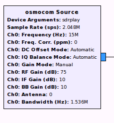 Let’s look at a flow for a simple radio (the same one you can see in the video above). Unlike the example in the previous post, I used the WX GUI system, but the same principles would apply with the QT libraries and blocks. The most important block is the Osmocom block (see picture to the right) that connects to the SDRPlay box. The properties of this block set the receive frequency, the bandwidth, and the RF gain. The RF gain configuration on the SDRPlay can be a little finicky. If you have it too low, you won’t hear anything. But if it is too high, you will overdrive and cause distortion.
I connected the output of the Osmocom block to two different strings of blocks. One branch is just an FFT so that you can see activity all around the vicinity the SDRPlay is tuned. The other branch is responsible for acting like a regular radio. Since the SDRPlay data is already shifted to zero frequency, there’s no need to do that. However, it does pay to cut off frequencies above the frequency of interest.
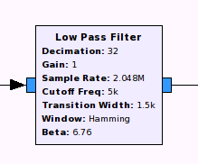 The low pass filter to the left takes care of that by chopping off everything above 5 kHz–plenty of bandwidth for an AM signal. In addition, I had the filter decimate the signal by a factor of 32. Remember, we need to go to 48 kHz for the sound card. Decimating the samples here will make it easier to further divide it down later and improve CPU utilization. The stage after the low pass filter is a rational resampler. This block divides (decimates) and multiplies (interpolates) the sample rate, allowing you to effectively multiply the sample rate by a fraction.
The output of the resampler is at 48 kHz and feeds an automatic gain control block and a demodulator. You’ll note the output port of the demodulator is orange, indicating it is a stream of real numbers, not IQ samples. The audio sink is the gateway to the PC’s speakers, but before the data arrives there the radio multiplies it by a value. The default value is 1, so it has no effect, but a GUI volume control can set that value to a different number to adjust the amplitude of the audio signal (in other words, the volume).
Mapping this back to a traditional superheterodyne architecture, you can think of the Osmocom block as the front end, local oscillator and mixer. The stages between it and the demodulator are similar to the IF stages of a classic receiver. Everything past the demodulator is no different from an ordinary radio’s analog amplifiers.
Radio GUI
Speaking of GUIs, this example as well as the last one, uses some GUI controls to change things like the volume and frequency. Each GUI block has a GUI hint that you can use to control where it appears in the running radio. You can use two or four numbers for each hint. The first (or only) two numbers are the row and column (both zero-based). You can think of an imaginary grid with as many rows and columns as you need.
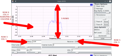
If you use four numbers, the first two are the same. However, the second pair of numbers specify how many columns and rows to stretch over. So if the top row, for example, has three controls in their own columns (hints of [0,0], [0,1], and [0,2]), you could have a control span the entire width of the window in the first row by specifying [1,0,1,3] in the hints (without the brackets which are just there for readability). You’ll see an example of this in the video. In addition, the image below shows part of the radio, illustrating how the top FFT spans 5 rows and 4 columns. Remember, the rows and columns are zero-based, so the next empty row is row 5 which is there the two controls that show the frequency appear (in columns 1 and 3).
If you follow along with the video, you’ll see that creating a simple radio with GRC is pretty easy. Obviously, you could improve the design both by making the radio receive better and by adding features like FM reception. My goal, though, was to make a bare bones setup that you could try to build upon before embarking on more sophisticated projects.
You can download the example files from the project page on Hackaday.io. You may need to adjust a few things based on your SDR adapter and your sound card, but if you have an SDRPlay and sound card that supports 48 kHz samples you should be good to go.
If you are looking for an actual project, consider this: Anything you can do with an RTL dongle, you should be able to do with the SDRPlay. If you search our past posts, you’ll see plenty of SDR projects based around that cheap device.


Why dont you guys just cover the cheaper RTL-SDR that more people use?
I fully agree, but with the example given there are not many AM broadcasts inside the normal frequency range of a $10-$25 RTL-SDR.
So to use a RTL-SDR you would need to pop the lid and solder extra wires for direct sampling. And add two filters a low pass filter front end from 14.4MHz down to DC, or a bandpass filter from 14.4 to 28.8MHz. Or you could use an up-converter in front of the RTL-SDR instead to shift DC-60MHz up to 125MHz-185MHz.
I bear good news from the future. RTL-SDR Blog V4 has a built-in upconverter and can receive AM radio down to 500 kHz. And the V3 has the direct sampling mod and can also go down to 500 kHz but with less reception so you’ll need a good antenna setup outside.
I followed this guide with a V4 and listened to 1400 kHz AM
I also bear bad news from the future – inflation hit and they now cost $30
If you search for RTL-SDR we’ve done a ton of coverage on it. I do have one. It isn’t terribly sensitive and doesn’t receive in the HF band without a hack (bypass wire) or a converter. Being a ham, I wanted to show HF coverage with a low bar to entry, plus the SDR box has a lot more capability than the RTL-SDR. On the other hand, you use the same block for RTL-SDR so if you have one, all the same things still work you just can’t receive HF unless you’ve done the converter or mod.
I have both devices. Unfortunately, I found out only after getting my sdrplay2 that the API/driver module isn’t OSS
You can use the RTL-SDR with GNU Radio.
You can probably also use http://www.pothosware.com/ to do the same above.
The aviation band from 108-136MHz is well within the range of the RTL-SDR and the signals are largely modulated with AM. Most people are within range of an Automated Weather Observation System at their local airport and that system tends to broadcast the weather 24/7 every day.
True, but what is the legality of rebroadcasting them ?
I’m not sure what rebroadcasting has to do with the scope of this video. If by rebroadcasting you mean using a SDR radio to retransmit the signal, then no, you shouldn’t do that. If by rebroadcasting you mean recording a video which has a short audio snippet taken off of the radio, then you are OK.
The point of bringing up the aviation band is that the demonstration covers AM radio reception and some commenters have lamented at the use of the SDRPlay in the video vs an RTLSDR radio. RTL radios are quite affordable, but the reception doesn’t cover anything below 30MHz all that well without the use of an upconverter. The GnuRadio demo can be duplicated by a reader, just not with the same stations. There is a viable AM modulated target to listen to with an RTL radio dongle; the AM reception can be had in the 108-136 MHz range instead of the DC to 30MHz range.
Great series of demonstrations by the way. Looking forward to the next in the series.
AG6WU
What I mean is recording emergency AM radio broadcasts from aeroplanes and uploading them in a video to youtube. In most countries, not all, this is illegal.
108-136MHz is the normal aircraft to ground AM band around the world. Emergency beacons are at 121.5MHz in this band.
The likelihood that any air to ground transmission (especially in the United States) is very slim due to the reliability of aircraft currently flying. Most traffic is routine in nature. As well (again, in the United States) there are no laws, to my knowledge, stating that you cannot rebroadcast air to ground transmissions. There are hundreds of sites that do just that, for what it’s worth. As this was recorded in the United States, and would be rebroadcasting aircraft in the United States’ airspace, there should be zero issues.
Brian de KF4ZWZ
Very timely for me since I recently bought an SDRPlay. Looking forward to reading the rest of the series.
One aspect that doesn’t seem to be mentioned in the article and that’s probably worth mentioning is image rejection. Suppose we choose 1000 KHz as our IF frequency and set our local oscillator to 6050 KHz. A signal at 7050 KHz will appear at 1000 KHz as expected, but if there’s another signal at 5050 KHz it will also mix with the LO and appear at 1000KHz right on top of our desired signal. This is called the image frequency and is always twice the IF frequency away from the frequency we want. A traditional superhet receiver needs a high enough IF frequency and a narrow enough filter in front of the mixer to make sure that signals at the image frequency can’t reach the mixer. You certainly can’t use an IF frequency of a few kilohertz or less like we often do with an SDR.
The reason this isn’t so much of problem with SDRs is because of IQ sampling. Roughly speaking, IQ sampling lets you have both positive and negative frequencies after the mixer. So in our example, our desired signal would be at 1000KHz after mixing and the image frequency would appear at -1000KHz, and we can use the I and Q samples to seperate the two. This is why we can safely mix our signal down to somewhere around zero hertz before feeding it to the demodulator.
I’d just like to say that this series inspired me to ask for an RTLSDR for xmas to try this stuff out. I’m a software person, but I’ve been doing hacky DSP at work and it’s been interesting. I want to expand my minimal knowledge into some nearby realms.
Just put sdrplay on Pc. No sound. Have sound card on 560 Dell pc. Instruction download does not tell me how to turn SDRPLAY ON AND OFF.
I have installed the GNU radio under my Windows, and couldn’t find a way to connect my SDRPlay box. can you give me a hint?
Great post. I suppose this was described for SDRPlay version 1. Is the code compatible with RSP2 ? (I am trying it with no success, yet) Is it (using gnuradio with rsp2) feasible with the currently available libraries ? Which would be the differences to take into account?
Al, Thanks for the videos and write-ups, they sure helped a lot to get me going with GNURadio. I notice you are using the Osmocom Source sdrplay device and that is what I want to use too. I’m running a Windows build of GNURadio, and my Osmocom Source doesn’t recognize the sdrplay device. Can you give me any help getting started to add sdrplay device to the Osmocom Source? Thanks.
Using an SDRPlay version 1, with Ubuntu 16.04LTS. I get “using device #0 Mirics MSi2500 default… usb_claim_interface 6…failed to open device.” any help here? Thanks.
I, too, am using the Windows build of GNURadio Companion Version 3.7.11. The Osmocom Source in my version also does not recognize SDRPlay as a valid device. Do I need to go to Version 3.8.xxx to get that? Or do I need to weedle it out of the SDRPlay folks?
I just got a SDRplay RSP2. The install and user instructions are junk.
To contact SDRplay, you have to register and give them marketing data.
Everyone seems to have problems getting it to run under Linux but the support is not there.
I’m looking for another more usable device.
“most important block is the Osmocom block” … yet the tutorial show it already included and configured. Even if one watched part one of the tutorial there is no idea where to get radio sources.
With a default install there is no osmocom block. I would have thought the tutorial at least mention how to get it into gnu-radio and show how/where on the right hand side you select it to add to the design.
I followed the video and programming very carefully but I have this problem with the Grid position on all my WX GUI Sliders staying red. I have entered the numbers like this 7,1,1,1 no spaces. The flow-graph won run because of these errors. I have tried it with spaces but nothing works. I have built simple FM receivers befor using the QT GUI widgets without problems.The error message is :
Error 0:
Block – freq – WX GUI Text Box(variable_text_box):
Param – Grid Position(grid_pos):
‘set’ object has no attribute ‘append’
Which I don’t understand.
Thanks for taking the time to help a newbe, Bob
Crystal sets with capacitors? The cry
stal sets I used to build had no capacitors