
Software Defined Radio (SDR)–the ability to process radio signals using software instead of electronics–is undeniably fascinating. However, there is a big gap from being able to use off-the-shelf SDR software and writing your own. After all, SDRs require lots of digital signal processing (DSP) at high speeds.
Not many people could build a modern PC from scratch, but nearly anyone can get a motherboard, some I/O cards, a power supply, and a case and put together a custom system. That’s the idea behind GNU Radio and SDR. GNU Radio provides a wealth of Python functions that you can use to create sophisticated SDR application (or, indeed, any DSP application).
If Python is still not up your alley (or even if it is), there’s an even easier way to use GNU Radio: The GNU Radio Companion (GRC). This is a mostly graphical approach, allowing you to thread together modules graphically and build simple GUIs to control you new radio.
Even though you usually think of GRC as being about radios, it is actually a good framework for building any kind of DSP application, and that’s what I’ll show you in the video below. GRC has a signal generator block and interfaces to your sound card. It even has the ability to read and write data to the file system, so you can use it to do many DSP applications or simulations with no additional hardware.
UPDATE: Don’t miss the follow-up post that uses SDRPlay to build a GNU Radio based receiver.
Building Blocks
There are several key building blocks that combine to make SDR possible. The first is some input device (a source) that is sampled at some sampling rate. For an audio device, the samples will be real numbers. However, radio devices will more likely provide complex numbers with an I and Q component.
If you aren’t familiar with expressing signals as I and Q components (sometimes known as quadrature data), that’s a big topic (with a great 3D explanation, one from Tektronix, and another one from National Instruments). However, you don’t need to directly understand the theory behind quadrature signals to get started with GRC. Just know that the I and Q signals can combine to express any waveform and, conversely, any waveform can break up into a series of I and Q values. With GRC, though, it isn’t that important (in most cases) to understand that, just like you can use a video card without knowing exactly what signals are on the PCI express bus.
A Starter GRC Project
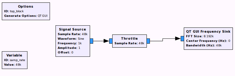 You can find a simple starter project on the video below. GRC uses a block diagram (a flow graph) to represent your project. When you create a new flow graph, you’ll see two blocks already present: one for options, and a variable named samp_rate. The most important part of the options block sets the graphical toolkit you want to use (WX graphical widgets or the QT widgets). For our purpose, it doesn’t really matter, but in the video I’m going to select Qt. The sample rate is so integral to your design that there is a special variable for it. Most other blocks will pick up the value of this variable and use it for their sample rate. However, this isn’t always what you want, but it is a good starting point. For this example, I’m eventually going to get input from a sound card, so I wanted a sample rate most sound cards will support (48 kHz). To start with, though, I kept the example very simple as you can see in the diagram above.
 To start with, you’ll place a signal source that generates IQ data (as complex numbers) on the flow graph. The signal generator block can actually generate too much data and slow down the CPU. Since the sample rate is 48 kHz, it doesn’t make sense to generate more than 48,000 samples per seconds. To make sure that happens, you’ll add a throttle block and connect it to the generator.
Connecting ports that have the same color (and, thus, the same data type) is simple. Just click on one port and then click on the other. The order doesn’t matter and you can connect more than one input to a single output. If the port data type doesn’t match, you’ll need to use a type converter (and the example video will show that later).
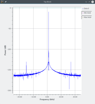
The final part of my simple example is just an FFT display block that uses QT (the same graphics library you set in the options block). Once it is all connected together you can press the play button and you should see an FFT of the signal.
Adding More
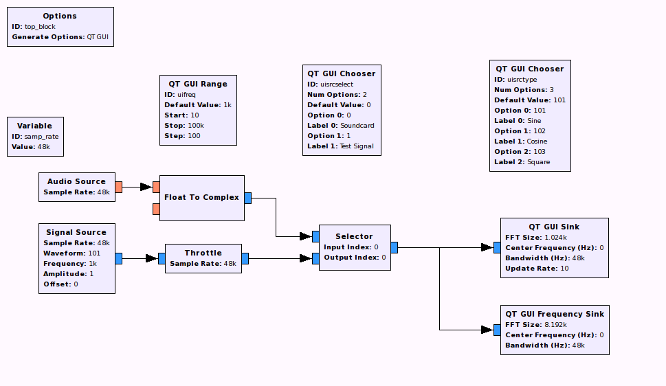 Granted, that isn’t terribly exciting, but you have to walk before you run. In the video you’ll see that you can add other graphical elements like sliders to change the frequency and selectors to pick the type of signal. Finally, you’ll add a sound card input (which does not need a throttle; in fact, in this case it is harmless to have both, but usually you’d remove the throttle block when using a real hardware block). What it does need, however, is a type conversion to change the real data to complex. The final project appears to the left.
I’d encourage you to watch the video with GRC open. You can get most of the way through without any special hardware and the sound card source should work with your sound card (surely you have a sound card in your PC, I’m guessing).
Once you are comfortable with the example, try extending it. Add a sound card sink to get audio out. Try filtering the audio from the test source. For example, what does a low pass filtered square wave sound like at different frequencies? If you are adventurous, try filtering sound card audio and writing it to a wave file for playback. All the tools you need are on the GRC tool palette.
If You Use PulseAudio
By the way, if you use Linux (like I do) and have PulseAudio as your sound system, you may get choppy audio playback. The fix for this is simple. Just create a file in your home directory: ~/.gnuradio/config.conf (or edit it if it is already there). You need the following:
[audio_alsa]
nperiods = 16
period_time = 0.100
You can increase nperiods even further if that doesn’t make it better.
Next Time
UPDATE: Continue on to build a radio receiver by example.
Next time I’ll break out the SDRPlay device and build a real radio. If you want a lot of detailed theory, check out [Michael Ossman’s] tutorial series. It is aimed at the HackRF, but the theory still applies. Of course, GNU Radio (and GRC) aren’t the only way to do DSP software, as we’ve noted before.


WoW man!! Thanks for the simple language and basics. Good for commoners like me, who actually need to learn to walk before running. Bonus is the link to IQ theory, I always wanted to know that.
If you use any linux system, step 1 is to get rid of the horrible pulseaudio and go back to alsa.
I have more problems with alsa than pulseaudio. As a matter of fact it’s alsa causing me problems right now with my audio on boot and nothing is fixing it, not even alsactl –store. Took me a year to figure out what the problem was thanks to people like you suggesting all sound problems are due to pulseaudio. Well, this time it clearly isn’t.
Choosing the audio front end is always going to depend on what works for you and what doesn’t. Luckily it isn’t terribly difficult to switch.
The hardest part about GNU Radio is installing it! If I can help it: I just boot up a copy of Pentoo linux when I need to use GRC. I have a dedicated ARM SBC where I’ve already paid the “suffering” tax if I need something more portable.
Just out of curiosity, Al, what distro do you use? I use Arch with a KDE 5 desktop environment, and I really like all the freedom it gives me for customization. As a bonus, I got to learn how Linux works, too!
I have used a lot of different ones, but tend to always use KDE up front. Right now I’m on Kubuntu. I am always impressed with the Arch documentation, so I’ve thought about trying it.
You should. One recommendation, though: try the makeiso image at http://www.evolutionlinux.com/ . It’s like the default installer, but comes with a couple tools on-disk to help you get started, like Midori, Gparted, and others. Best part is, it just installs Arch, not some custom-variant like Manjaro.
Arch installer with gparted built in, you say? I know what I am doing today…
Did I miss the part where they said what the hell GNU stands for?
http://www.gnu.org/
“GNU’s Not Unix!”
https://en.wikipedia.org/wiki/Recursive_acronym
Alsa/Pulseaudio ? GNU ? Linux distro ? How about some SDR :D
But yes on a related note, best way for someone to try out GNU Radio for the first time would be to try a live Linux system with GNU Radio already installed. Like the one mentioned by iamthewalrus above (Pentoo Linux) or Kali Linux etc. Just enjoy it while it lasts.. :) (and I don’t need to mention for a start $10 SDR can be enough) Once you start getting into a serious relationship (with SDR), get a installed Linux version rather than the live one (most live distro give you that option) and get a serious HW. (This would only happen if you are able to break the ice and above tut should help a lot ;) )
OK, but I what if I want to do real radio? With 10 GHz carrier frequency and 100 MHz bandwidth. I need first an DAC that has the 100 MHz analog bandwidth, at least 4.5 Enobs and at minimum 200 Msample sampling rate. Then I need a 10 GHz signal source and a mixer to upconvert it. On the receiver side I need a corresponding ADC, and of course a mixer. I did a lot of radio over fibre with offline processing and basically SciPy/Scilab/Matlab are fine. C++ is better for speed, once the algorithms are tested.
You might want to first consider that 100mhz bandwidth at 10ghz isn’t legal across most jurisdictions covered by the ITU. The emissions power is limited in this area as well. Depending on what you want to do, there are other bands that might be suited better
of course – everything is illegal.
Of course everything is not illegal. Although many self absorbed wannabe resource hogs wouldn’t understand.
That would be a silly thing to want in a “getting started” article. Gnuradio companion is a very good learning and prototyping tool, much better than doing it in the things you recommend.
Also, real radio is a bit snobbish. VLF is as real as SHF.
I think I’m going to move onto the embedded/FPGA side of things. The GNU radio package has always been so incredibly poorly documented that I find it hard to do anything that isn’t exactly like that they have in the tutorials.
There is also a great video series by Michael Ossmann over at Great Scott Gadgets on SDR. This is what I used to get started with SDR.
http://greatscottgadgets.com/sdr/
Hello Al Williams and the rest of Hackaday,
I’m a graduate student and licence amateur radio operator. I’m studying aspects of the Automatic Packet Reporting System (APRS) which is a radio messaging system used all over the world. http://www.aprs.org/
One aspect that I’m looking into is how Doppler Shift impacts the reception of messages (induced errors). To do this I’m using a HackRF One and GNURadio Companion. I’m using the HackRF as a transmitter on 144.39 MHz for North American APRS. I need the GNURadio to do fine adjustments to emulate the Doppler Shift.
I’m having a problem feeding the GNURadio the right types of data strings for transmission.
I started out using PyBombs to add the needed blocks:
http://gnuradio.org/redmine/projects/pybombs/wiki
I’ve made a fair amount of progress with Tim K’s GitHub code so far:
https://github.com/tkuester/gr-bruninga
But I don’t think I’m feeding the input to the Socket PDU properly.
His block arrangement is “Socket PDU” into a “String to APRS”
https://drive.google.com/open?id=0BwvDU4wQSFTxcWl0WHJBczVRNWs
I’m not entirely sure if the “String to APRS” block is actually parsing the strings appropriately for APRS:
http://www.aprs.org/doc/APRS101.PDF
basically there are Flags at the beginning and end of each packet to tell the receiving radio that the packet is finished. This creates pauses in the horrid screeching sound you’d normally hear if listening to the raw RF channel. If I feed a large string (a bunch of text) into the Socket PDU over Telnet, the stream of noise doesn’t stop and my receiving radio (a separate system) doesn’t interpret this screeching back into data as we’d normally expect.
Either way I’m looking for some help from the community of talented people that is Hackaday.
Thoughts?
Why don’t you just check the block’s documentation?
Let me guess… there probably isn’t any. Or it’s thoroughly inadequate. Our out dated.
All of the above really. At this point I’d need to track down this Tim fellow and call him on the phone.
I’m thinking its my lack of understanding of how Socket PDU works and how little there is documented about the “String to APRS” block.
I’m not much of a coder. I’m not a huge fan of Linux either. So…there’s that not helping me…
My experience with GNURadio has been….interesting…..but more frustrating. I’ve got a coder friend helping me whom I’m slowly driving insane with a “simple” task of adding a block, with math that I’ve provided, into GNU. Its not going well.
This is the best – only – tutorial I have ever come across that has allowed to make progress with GNURadio – superb job Al. Looking forward to the next ones
Great article!