Ceramic capacitors are small, they don’t leak, they’re convenient, but they are downright strange. Certain types of caps will lose their capacitance depending on the voltage they’re operating at. If you’re using ceramic caps for filters, DC to DC power supplies, bypass caps, or anything where you need an exact capacitance in a circuit, this can be a problem.
[Mathieu] has come up with a tool that’s able to measure the capacitance of a cap over its entire working range. He’s calling it the OpenCVMeter, and although the name might be slightly confusing, the functionality is not. This little box will measure the capacitance of a part over a voltage range from 1.3 to 15.5V.
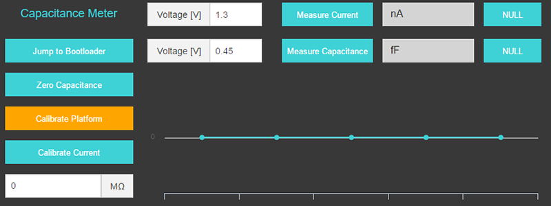
By attaching the SMD tweezers or test clips to a capacitor, the OpenCVMeter ramps up the voltage and measures the capacitance of the part through the test cycle. This data is then dumped to a Chrome app – a surprisingly popular platform for test equipment apps – and a determination of the cap’s ability will to work in a circuit is displayed on the screen
If you’ve ever tooled around with antique electronic equipment, you’ll know the first thing to go bad in any piece of equipment are caps. Either caps had extremely loose manufacturing tolerances back in the day or the values really were that critical, but a dodgy cap can bring down everything from tube amps to computers. It’s a very neat tool, and something that doesn’t really exist in a single dedicated device.


I believe the old- but still very powerful- ESI VideoBridge is actually capable of performing these types of tests.
Aren’t only electrolytic capacitors prone to failure from age due to the liquid electrolyte drying? (Though all caps can fail for a variety of reasons).
I thought ceramic capacitors were a separate issue.
Paper wax ones will also fail from age, and a lot of antique gear use them. I believe also mica ones can fail from age and exhibit some very very odd symptoms when they do so too, such as not immediately displaying their failure or testing good on a meter but not when put into the circuit and enclosure in question.
Tantalum caps also fail with age-related issues, especially if they’ve been unplugged for a long time.
And when they fail they fail quite spectacularly, I had a large in a power supply suddenly just •pop* sending a glowing red hot chunk of tantalum flying through the air landing on the carpet with me scrambling to find something to pick it up.
So why did you remove the PSU from its enclosure in the first place..
It was an open frame power supply.
…able to test a ceramic cap over its entire working range 1.3v – 15.5v. Don’t ceramic caps have working voltages of 50v+?
I have been thinking exactly that.
Tiny SMT ones have lower voltages to get them smaller.
50V 0402 size is no problem. The 15v is a big limitation. Should have had an external voltage input.
I designed the device to measure capacitance at the most commonly used voltages.
Some ceramic capacitors have been manufactured with very high capacitance, relative to other ceramic caps, and low voltage. Like 10uF at 15V. But they suffer from large changes in capacitance with applied voltage.
Why not just use an electrolytic, which you can get at much higher capacitance? Because an aluminum electrolytic is made by winding foil into a cylinder, and so has high parasitic inductance. The ESR tends to be greater than that of ceramic capacitors.
The high value ceramic caps are made with many paralleled layers of metal and dielectric ceramic, so the parasitic inductance is very low. This is important for bypass applications like switching power supplies and circuits with high peak to trough current ratios.
Higher value ceramic capacitors use ceramic formulations with greater dielectric constants. Disadvantages are lower breakdown voltage, piezoelectric effects that make them both detect and give off sound, changes in capacitance temperature, and changes in capacitance with applied voltage.
I would never use one of those high value ceramics in anything requiring tight tolerances. Like an active filter, or a passive filter that requires anything more than generalized lowpass or highpass filtering.
Are there any ceramic caps with a voltage rating of 15V or less? Usually it’s at least 60V.
Plenty. I think 6.3 V is the lowest common rating.
Yes, 6.3V is fairly common, but there are a few 4V and even 2.5V types.
The high value MLCC have low voltage ratings. There is only so much dielectric in small packages when you are pushing C up. 1/2 CV^2 I have seen 4V 10uF in 0603.
Didn’t know they made ceramics in such high capacities, thought that was just electrolytics, or tantalum. Technology, eh? And yeah I was thinking of the traditional round, wire-ended ones, rather than the teeny SMD type.
SUUUUPER useful. SMD ceramic capacitors derate so spectacularly badly that’d I’d be concerned with even decoupling caps. That through-hole 0.1uF @ 5V decoupling cap might require a “1.0uF 0402” @ 5V to filter 5V rail noise similarly. Worse than that, from most of the datasheets I’ve seen (I basically only shop cap manufacturers with rated CV curves now) don’t even get better with higher rated voltage (in fact, the CV curve tends to be same; you can just put more voltage on it safely)
For decoupling of digital circuits, the package and the PCB layout dominates over capacitance for high frequency. Your through hole part has the capacitance, but loses out in the long leads, mounting height above PCB (large loop area). The 0402 part works better for modern circuits.
Here is a really interesting article that goes into a bit of detail about the reason why this is such a cool device:
https://www.maximintegrated.com/en/app-notes/index.mvp/id/5527
wow… that’s a nice find, thanks!
What’s the deal with people claiming “Open Source” but not having open source?? Someone show me I’m being stupid and post the design files for this kickstarter?
This is all I can find:
Mathieu Stephan
https://hackaday.io/limpkin
http://limpkin.fr/
https://hackaday.com/author/mathieustephan/
I’ll write a detailed article on my website in the coming days with the schematics.
Interesting project, but i would prefer to have a wider voltage range too. We work a lot with 24V and 48V supply voltages in our appliances, so 50V and 100V rated capacitors are very common for me. Even the standard 100nF decoupling capacitors in 0402 package we use are all rated for 50V. We only go lower in voltage raiting if we need larger capacity in a small package. Well, maybe once they release the hardware design we can make an improved version where you can set a higher voltage and loose some precision, or work with lower voltages and get a higher resolution.
Something else i would like to see is an extension to a complete RLC meter that could give some estimated values for series inductance and resistance in the capacitors. Probably not that easy to do with the long test leads tho, if not calibrated properly.
Actually you could put a power supply in series with the leads to increase the voltage.
I’ll write a detailed article on my website in the coming days with the schematics.
Hi, maybe there are people who need this kind of measurement everyday, and in this case this might be a useful tool.
However, you can do exactly the same measurement with any other capacity meter.
The only thing you need to do is to decouple the DC offset voltage from the measuring circuit.
Option one: Connect two identical specimen in series in the test circuit, and apply the DC voltage via a 10-megaohms resistor to the middle node.
Option two: If you have only one specimen, connect a known second capacitor (or one with a capacity two or so orders of magnitude higher) and do the same measurement.
Also, the C(V) characteristic that you encounter at some specific environmental temperature and at a certain mechanical stress situation is a pretty useless value in an application.
What counts in an application is to have known upper and lower boundary values for the permissible deviation from the ideal C(V) characteristic curve, and for this you need only read the datasheet if you are not recycling parts.
I admit that you can deduce that property from the measured curve in most cases
The capacitor under test can provide the isolation. You’ll need an isolated power supply, then you lift the ground lead of the capacitor under test and apply a negative bias voltage to it. I would only turn up the voltage after it is all connected, to avoid a sudden charge current into your capacitor tester.
Then the bias voltage is the power supply voltage and the voltage applied by the capacitor tester. In the case of the EDN circuit, it only applies about 600mV plus or minus about half a volt. So if you want to test it at 5V, set your power supply voltage to 4.4V. If you are testing at 50V or higher, you can probably ignore that tiny offset.
“Also, the C(V) characteristic that you encounter at some specific environmental temperature and at a certain mechanical stress situation is a pretty useless value in an application.
What counts in an application is to have known upper and lower boundary values for the permissible deviation from the ideal C(V) characteristic curve, and for this you need only read the datasheet if you are not recycling parts.”
Agreed.
I should say, I’m assuming short wires from the power supply providing the bias voltage, and low ESR capacitors in the power supply. Or a capacitor rated at sufficient voltage, with low ESR and capacitance at least 10x that of the capacitor under test may be inserted in parallel with the bias supply right at the capacitor under test.
Worth repeating I think, any time the failur erate of old capacitors is being discussed…
When an old device has not been powered on in a very long time charge the capacitors slowly. Depending on the design of the device it may be as simple as plugging it into a variac turned to minimum and slowly increasing to line voltage. Or.. it may involve taking the device apart and powering up specific sections individually, starting at far less then their normal working voltage and slowly turning it up.
Do this and many of those capacitors will be re-formed.. they will not fail. Now you can turn it on normally next time.
Then again… they are still old caps and probably a bit off in value. As an alternative.. just replace them all BEFORE you power up. That prevents you from inadvertantly damaging other parts when those old capacitors turn into shorts (or fire).
Either way.. DON’T JUST PLUG IT IN AND TURN IT ON!!!!