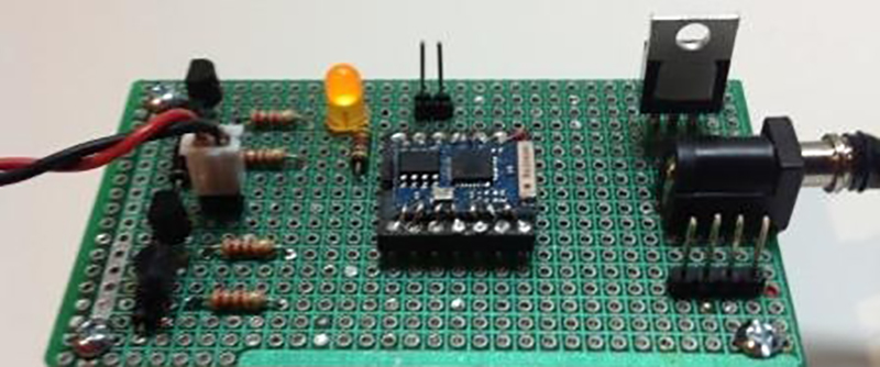
Even in the face of an Internet of Things grasping for a useful use case, an Internet-connected clock is actually a great idea. With a cheap WiFi module and a connection to an NTP server, any clock can become an atomic clock. [Jim] decided to experiment with the ESP8266 to turn a cheap analog clock into something that will display network time using a bunch of gears and motors.
The clock [Jim] chose for this build is an extremely cheap clock pulled right from the shelves of WalMart. This clock uses a standard quartz clock mechanism, powered by a single AA cell. The coils in these quartz movements can be easily controlled by pulsing current through them, and with a few a few transistors and diodes set up in an h-bridge, an ESP8266 is quite good at setting the time on this clock.
The software for this clock first connects to the WiFi network, then checks an NTP server for the true time. Once the ESP8266 gets the time, it starts hammering the coil in the clock movement until the hands are where they should be.
[Jim] says the project needs a bit of work – there is no feedback on the clock to determine the position of the hands. Instead, the time is just set assuming the clock hands started off at 12:00. Still, even with that small fault, it’s a great build and a great exploit of what can be done with a cheap quarts clock movement.
If you’d like to go to the opposite extreme of cost and complexity, how about a DIY retro atomic clock? Or if you’re in need of a wakeup, we’ve seen a ton of alarm clock posts in the past few weeks.


The extra transistors are not necessary. A typical clock chip drives the clock motor with several mA, e.g. the H1344 (first google hit) specifies min. +/-4mA at a motor coil resistance of 200 Ohm. The GPIOs of the ESP8266 are stronger than that.
I would just add a serial resistor to the motor coil (or use very short pulses) because the ESP works with more than 1,5V).
Another idea: Use something like an SFH900 reflexive opto coupler for reference detection. If it is triggered by both hands, then you get a pulse every 3600 pulses from the minute hand and an extra one from the hour hand. with a good position (NOT the 12 o’clock point) you can distinguish this in software.
Assuming the clock mechanism needs second impulses (60 per minute) I think it would be good to set it on the 1 minute before 12″ position. So it will be activated by the hour hand just before it reaches 12 o clock for at least “5 minutes” (300 impulses on the motor), then as the hour hand leaves it, very soon after that it will be activated by the minute hand for “1 minute” (60 impulses). If it is then “open” again you have reached the 12 o’clock position.
Or wire the transistors as complementary emitter followers and do away with the 4 resistors. Emitter followers has a base-emitter drop, so for both paths that works out to drop 1.4V or so.
If driving from ESP directly, consider using much faster switching diodes instead of rectifier diodes for protecting the I/O.
I am not absolutely sure about the ESP, but normally CMOS outputs have protection diodes which serve as freewheeling diodes for this small current. If you use the emitter followers you waste not less energy than with the resistor. And a transistor is typical 10 times more expensive than a resistor.
But instead of using a series resistor and wasting some energy in it, you can adjust the length of the driving pulse so that – together with the inductivity of the motor winding – the current reaches exactly the right value. I know of clock driver ICs which do that to compensate for a depleting battery. They are designed to use just the right amount of power to drive the hands but not waste any energy with overdriving so it gets the maximum battery life. I think this chips measure back EMF to decide if the motor really turned with the right power. If not they adjust the drive pulse length automatically
Of course this is not necessary in this application, as the power consumption of the ESP module is greater by some magnitudes .
It is simply enough to drive the coil with two GPIOs. The goal is not to use more components than necessary, it is to use as little components as necessary :-) If the ESP has no protection diodes (unlikely, but measure them) some BAV99 or 1N4148 are sufficient and they are fast.
That’s really interesting, how do they measure the back EMF?
Unfortunately it is >10 years, that I read the datasheet of this chip, so all this is quite sketchy. I can imagine, that they tested the voltage after the pulse ended. Perhaps the decay of the voltage. The apparent inductivity and generated voltage are sure dependent on the motion of the armature.
They could simply measure the voltage across the inductor or the driver transistor (inductive current) vs a preset threshold using a comparator/reference inside the chip.
I wouldn’t drive the motor with external switching diodes. There is quite a bit of inductance in the motor coil so that’s going to a lot of stored energy in the inductive kickback on internal ESD diodes. Diodes or transistors are 2 orders of magnitude cheaper than the WiFi module. You are better off claiming that it could result in a smaller perf board to save money. :P
FYI: 100 (1N4148) switching diodes are $0.86 while 100 transistors costs $1.79. Both comes with “free shipping”.
On seeing this, I did think of maybe hacking Radio Controlled Analogue Clock, that way, you have two sources for your time signal and good midnight sensor built in.
Over kill maybe but still an interesting project. Maybe even add Lord Vetinari time keeping.
Maybe just use a reed switch or a Hall sensor with a small magnet on the hour hand? Sure, may need 1 more GPIO, but then it’s fully automatic.
Or an ir receiver set back in the face with a pinhole (to avoid stray light) out to the hands. Drill the hour with a small hole, add an ir emitter on the back of the minute hand. Only when the two hands line up over the holes do you get the signal.
I was thinking of using a PWM controlled servo motor, let the position be set by the duty cycle… Might not give the prettiest result as it’d need to do a full turn every once in a while (depending on the servo, I suppose) but without a sensor I don’t really see a way.
I’d use a PWM controlled servo motor, let the position be set by the duty cycle. Might need to do the occasional full rotation though…
I also have been working on an ESP2866 based NTP clock, but happens to have a very different interface :P
https://hackaday.io/project/8327-light-alarm-clock
Really need to get around to finishing the documentation, but it’s pretty simple overall.
I’m assuming the H-Bridge is required to reverse the polarity of the coil. Couldn’t this be done with a 5th transistor and create a flip-flop that’s driven by a single Pin? Then, use the other pin as a feedback for the hour hand and you’ve got a closed system.
Lastly, how hard would it be to rewrite this to have the a “Vetinari clock” tick scheme?
No. Those cheap Lavet motors can be controlled by a capacitor and two optocouplers.
Very cool! Especially if you have this stuff laying around. Below is an anecdotal story in which another option is realized. Trust me I ‘get it’ but thought others may be interested as well.
Last year I decided I wanted an atomic clock, but I also wanted and appreciated analog hand movements (and ticking sounds!). After some searching I bought this last year for $15 on sale. amazon.com/gp/product/B0001PG238 .
Money well spent IMO. And because it uses radio signals instead of network connectivity, there are far fewer dependencies or reasons the clock may not display the correct time..
I’m a little confused.
This will be accurate only once after you set it from the 12:00 point? What happens in 3 years. Are you compensating for drift? Are you setting the 12.:00 starting position by hand? Feedback seems necessary in this instance.
Perhaps I didn’t explain it clearly in my article. The lack of feedback only means that the ESP8266 doesn’t know the starting position of the clock’s hands. That’s what the “analogClockSetup” script is used for. The hands can start anywhere, just tell the ESP8266 where by filling in the fields on the web page that the setup script serves. Once the ESP8266 knows the hand’s starting position, it keeps track of the hand’s current position based upon the number of “ticks” which move the second hand.
“Drift” is not an issue. The ESP8266 connects to the NTP server every 15 minutes, in between connections it keeps track of time based on its internal oscillator . If the internal oscillator is off a bit, and as a result, the analog clock has gotten ahead of or behind the server time, the ESP8266 will skip “ticks” (if the analog clock is ahead) or add “ticks” (if the analog clock is behind) to reconcile the analog clock with the server the next time it connects.
I tried this once, and failed. I found that over time the position of the hands becomes inaccurate, even though the clock I used was GPS disciplined (I used the PPS output after confirming it was accurate). I tried all sorts of unipolar and bipolar motor driver schemes and was even able to duplicate the original driver’s waveform. But nothing worked. After a few days or a week the time would be either fast or slow by up to several minutes.
Can anyone provide URL to buy ‘Lavet motors’, please?
Most cheap clocks have one inside. I bought one at reichelt.de , search for “QUARZWERK”, it is insane cheap with less than $ 3.