
The number of hours we spend staring at screens is probably best unknown, but how about the technology that makes up the video on the screen? We’ve all seen a reel-to-reel projector on TV or in a movie or maybe you’re old enough to have owned one, surely some of you still have one tucked away real nice. Whether you had the pleasure of operating a projector or just watched it happen in the movies the concept is pretty straight forward. A long piece of film which contains many individual frames pass in front of a high intensity lamp while the shutter hides the film movement from our eyes and our brain draws in the imaginary motion from frame to frame. Staring at a Blu-ray player won’t offer the same intuition, while we won’t get into what must the painful detail of decoding video from a Blu-ray Disc we will look into a few video standards, and how we hack them.
Observations at a glance
I’m sure most of us have noticed that an HDMI connector has quite a few connections, 19 pins make up an HDMI connector. Are all of those pins for carrying video from the set top box (insert your media player) to the display, or is there something else going on here? HDMI is orders of magnitude better in quality than any VGA monitor I’ve ever owned. I know VGA uses a 15 pin D-SUB connector, but you need to know that not all of the pins carry unique signals through a VGA connection, nor are all of them carrying part of the image we see on screen. Looking even further back into the history of video gets us to composite, one glorious yellow-tipped RCA cable. Beauty in simplicity it was, a single signal wire and a shield.
Composite
A composite video signal is carried over a single shielded conductor. The signal is broken up into frames and frames are broken up into lines. This is nothing like it sounds, a frame is a static image that covers the entire screen of the display and a line is a smaller unit spanning from the left edge of the screen to the right edge stacked one on top of each other from the top of the screen to the bottom, making up a frame. Is that what it sounded like to you? Well then I suppose it is exactly how it sounds, isn’t it.
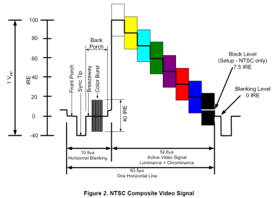
The composite signal is broken up into smaller signals representing horizontal lines which are separated by sync signals as seen in Figure 2 (I can’t tell you what happened to Figure 1, it must have snuck out the back when you got here). The picture we see on the screen can be found in the active portion of the horizontal line signal. The amplitude of the signal is responsible for the brightness while the color information is included as a sine wave added to the brightness signal. The colors can be identified as differences in phase between the color burst reference and the signal phase. In a more digestible version: The intensity of individual colors is determined by the amplitude of modulation while the tint is determined by the phase.
That’s not much fun and the amount of non-video information here is minimal, only including the horizontal and vertical sync. The horizontal sync can be seen in the blanking portion of the signal while the vertical sync is added after the last horizontal line of the frame. It’s not necessarily as anticlimactic as it may seem, the low complexity of this video standard lends itself to easy video creation by 8 bit hackers. You can find plenty of implementations of this done in black and white incorporated into 8 bit arcade clones like Hackvision, a controller shaped PCB with audio and video out running on an ATMega328. We’ve also seen [CNLohr]’s color video done with an 8 bit AVR.
VGA
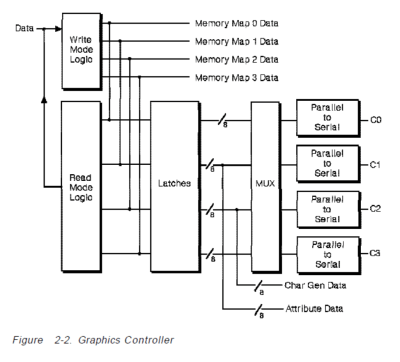
Video graphics array (VGA) reigned as the standard for quite some time. With a resolution of 640×480 – 16 color or 320×200 – 256 color (“Mode 13H”) and sometimes flicker-free video it was a dream come true. Although the time taken to draw a single horizontal line with VGA was twice as fast as composite there were still improvements to be made. Those left wanting more could change the graphics controller code to their liking. This became very popular and finding code and/or help with writing your own code was widely available. One of the methods made publicly popular by [Michael Abrash] was referred to as “Mode X” which [Abrash] shared in his column of Dr. Dobbs Journal. Mode X was interesting in that is was not documented by IBM, yet it was arguably the best mode for developers which in turn was better for the users. The advantages of Mode X were quite large in comparison to its other available modes, as [Abrash] states 5 main advantages in his book Graphics Programming Black Book:
- Mode X has a 1:1 aspect ratio, meaning you can code a circle as a circle without having to take into account a stretch which resulted in coding an ellipse to display a circle.
- Mode X utilized memory page flipping rendering smoother animations.
- Allows plane-oriented hardware to be used when processing pixels in parallel, which amounts to a 4x improvement over Mode 13H.
- Mode X and Mode 13H both have the byte-per-pixel mode for controlling each pixel with a byte of memory, which the other modes did not have. To deal with this the other modes had to bit-mask as each byte contained data for more than one pixel.
- Mode X in comparison to Mode 13H had a surplus of available off-screen memory to store image data and write it into the display memory 4 bytes (or 4 pixels) at a time when used with the inherent VGA latches.
Though Mode X was not easy to program for, it was worth the effort and not such a daunting task for an experienced VGA programmer in combination with good documentation such as [Abrash’s] book.
The VGA connection is a 15 pin D-SUB of which there are 3 conductors for the color video signal. These are the same that make up component signals Y-Pr, Y, and Y-Pb. This leaves 12 more pins on the connector, or 11 if you have a keyed connector. Six more of these conductors are dedicated GND signals, we do have a horizontal sync as well as vertical sync leaving 4 conductors unaccounted for. We’ll leave 2 of them alone and only point out that there is an I2C bus within VGA on pins 12 and 15 which are SDA and SCL respectively. These lines can be hijacked and used as standard I2C pins depending on your hardware and operating system. As you might imagine, this is not a new concept as you can see one of the best examples we have found is on the Paint Your Dragon blog and dates back to 2008.
Hack VGA into your 8-bit microcontroller projects is quite a bit more difficult than it was for composite video. Timing becomes an issues with the increased speed of VGA scanning. But it can be done. We’ve seen the Arduino do 640×480 with 8 colors and more recently it was used on a PIC24 by [Arko] for the LayerOne Demoscene Board. After all, that’s what demoscene is all about; more glitz with less bits. ARM generally has more speed so we’ve seen VGA there as well. But what truly shines for VGA is FPGA hardware. It is a straight-forward protocol to implement and the massively parallel nature of FPGA hardware means this is a class assignment for pretty much every college-level FPGA course out there. What’s more awesome that getting course credit for implementing Meat Boy in an FPGA?
HDMI
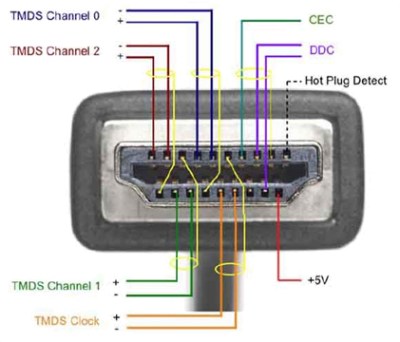
High Definition Multimedia Interface (HDMI) the first noticeable difference is that this protocol also includes the transmission of an audio signal. More specifically, HDMI 2.0 delivers 32 channels (4 streams) of audio and dual stream video. The 19-conductor pinout contains 3 sets of shielded, twisted, differential signal pairs (that’s a lot of buzz words that sum up to ‘high speed’).
To be more specific the data lines use a technology called “Transition Minimized Differential Signaling” (TMDS). There are three channels of TMDS used in HDMI and each channel consists of the data-, data+, and shield conductors. It is worth mentioning that the shield for each pair is isolated to an individual pin rather than all tied to the same outer shield of the connector and eventually to the ground plane as we see commonly in USB.
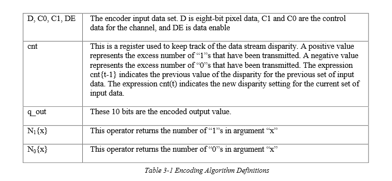
In order to recover the clock signal and sustain signal integrity the bits in the stream of data need to be balanced. TMDS uses a modified version of the standard 8b/10b encoding used in the telecom industry. The idea is to balance the number of 1’s and 0’s in each piece of data which is 8b in length. The 9th and 10th bit describe how the balancing was achieved. The first stage is started by using an algorithm to determine how many bits are set in the original byte. By systematically modifying all bits except the LSB the system gets closer to a balanced number of 1’s and 0’s. If there are more 1’s than 0’s or there are 4 of each then we move into the XNOR system. As stated earlier the LSB (D[0]) is left unchanged and its value is used to determine what will be held in D[1] by XNORing D[0] and D[1] and placing the result into D[1]. The process continues by XNORing D[1] with D[2] and placing the result into D[2]. So on and so forth until D[7] XNOR D[6] and placed into D[7], the system now needs to leave information stating that an XNOR process was used as opposed to an XOR, which would have been the case if the original byte had more 0’s than 1’s. This is done by setting D[8]=0 for XNOR and D[8]=1 for XOR. The second part of the encoding process is to invert the first 8 bits if necessary to balance the 1’s and 0’s. The 10th bit is set if this inversion took place. Now the data is balanced and ready to be sent to another device.
This is getting beyond the realm of pedestrian embedded hacks. That doesn’t mean it can’t be done, we’re just a long way from composite video now. One of our favorite HDMI hacks is still [Bunnie’s] man-in-the-middle that allows video overlay.
The data lines in the TMDS channels only make up 9 of the conductors, there is also a TMDS twisted pair for the clock signal, putting the conductor count up to 12. We have covered how the picture data is encoded and transmitted at speeds up to 2.25 GB/s for HDMI 2.0 now let’s have a look at some of the other conductors and what they are used for.
HEC/ARC
HDMI Ethernet Channel (HEC) and Audio Return Channel (ARC) are both assigned to pin 14, and I can say that I have used the ARC function to send an audio signal from the television to the stereo receiver. But I have never, to my knowledge used the HEC function nor have I come across a real world application for this feature. I’m sure they exist, if you have used the HEC in an HDMI connection tell me about it in the comments below.
I2C
Pins 15 and 16 are dedicated SCL and SDA respectively and this is where the High-Definition Digital Content Protection (HDCP) takes place. We covered an example of using a splitter to decrypt the HDCP back in March.
Conductors++
Its clear the advancement of technology cause video standards to have more conductors, but is it necessary? After all isn’t most broadband delivered via coax cable? The bits that come into my house plug into the router via single shielded copper conductor with the burden of carrying the entire inter-webs and hundreds of overpriced cable channels that we don’t want or watch. This is then distributed throughout the house to devices and displays which use more conductors by several orders of magnitude to deliver the last stages of that signal.
My estimation is that conductor counts will continue to rise as they have done, but what communication protocols will be used and what new features will we see? Is I2C the set-in-stone communication protocol for video? Will Intel continue to use I2C for HDCP or is it time for a change? What do you think the next standard will be?


How about DisplayPort?
DisplayPort, HDMI, and DVI are all v\kissing cousins.
If you incest…
Usually VGA is RGB, not Y,Y-Pr,Y-Pb. Some RAMDACs have a Y,Y-Pr,Y-Pb output mode, but often a converter is needed to get Y,Y-Pr,Y-Pb signals from an RGB source.
VGA is usually RGBHV not RGB. Very big difference.
VGA is indeed RGBHV where the RGB stand for pure analog display levels and the HV stand for separate lines for horizontal and vertical sync.
But that’s quite different from Y,Y-Pr,Y-Pb where Y is luminance and the other two are the difference between blue and luminance and red and luminance.
Although confusingly they are both refereed to as ‘component’.
ALWAYS VGA is RGB! At least the signals that come out of a VGA socket to feed a VGA monitor. The stuff on Mode X is a bit confused too.
The bit about composite is also wrong. Colour is encoded on a separate carrier wave, encoded as phase AND amplitude. Which is how you can fit 2 signals, U and V on to it. And that’s about as far as I understand, PAL / NTSC colour is pretty weird. I can understand it for minutes at a time then, gone! Where did the green signal go?
For a primer, this article isn’t great!
While I’m complaining… Mode X is also completely irrelevant. It’s been obsolete for decades. Nothing runs in 320×200, or the 320×240 hack mode. And you can’t access video RAM directly on modern PCs anyway, or at least, that’s not how it’s done. It’s all through libraries, cooperating with the OS. Not like DOS where you could send bytes wherever you liked. Although Windows will emulate Mode X, and 13H if you try that.
There’s nothing wrong with his explanation of composite video – it’s exactly correct.
I see you have correctly translated his words “sine wave” as “carrier wave”, which are one and the same thing. You have also correctly regurgitated his words “individual colors …determined by…amplitude … while the tint is determined by the phase” and said “encoded as phase AND amplitude”.
Well done – you have nicely repeating what was already correct :)
No, he said that amplitude determines brightness. Which it does, on the B&W / Luma part of the signal. But the colour isn’t stored as phase on that signal. There’s a separate carrier, which uses amplitude AND phase. Because there’s 2 things to encode, U and V.
He mentioned the colour subcarrier, but didn’t mention that it’s amplitude modulated as well as phase. That’s the very specific nit.
Though the whole thing’s pretty confusing, the way colours are stored and encoded. Sure it’s the best way they could do it at the time, a complicated scheme that met the requirements of what was possible, and what was needed (like compatibility with old monochrome sets). It’s easy to forget one part while you’re thinking about another, at least for a layman.
What he said is exactly right. Your a complete idiot. Different frequencies and phase combine when they was placed on one carrier.
Oh RÖB.
If you’re going to call someone a complete idiot, at least use the correct “you’re.”
@[notmyfault2000]
I often wonder what makes someone’s life so sickeningly boring that they have to take to the internet as “grammar police”.
Er, Rob, that’s not what I’m talking about. So that means… you’re an idiot! I bet this idiot-calling could carry on for years.
@ [Greenaum]
Quote: “you’re an idiot! I bet this idiot-calling could carry on for years”
No not years, but long enough that others form their own opinion as to which one of us is an idiot.
Good luck with that!
PAL / NTSC colour *IS* composite video. They are two different standards of exactly that: composite video. If you don’t understand PAL / NTSC, then how can you say that what he says about them “is also wrong”.
The problem is that in video standards they re-use the same word for different things, like component and composite,
Where the issue is that people for convenience drop the elucidating definition of what kind of composite or components they are talking about, assuming that people will infer it.
The Coax internet solution is effectively a radio that is confined into a wire. The differential signalling allows for a cheaper (to manufacture) cable, and cheaper (to decode and process) data channel, with higher bandwidth, and lower latency.
To generalize, Coax is basically multiplexed on frequency. While multiplexing can reduce the number of conductors, it can increase the complexity of the receiver and sender. While Coax can run miles, is it worth adding cost to the sender and receiver for a 3 foot cable, or just add more wires?
Depends. How far does that signal need to travel. You need a transmission line such as coax to reliably send signals further than a few dozen feet.
HDMI and such can do quite a distance,
My powered hub lists 82 feet as a distance for transmitting and 50 feet for the feeding line.
If I am so rude as to combine the two (perhaps not fair) I get 130 feet, which is 43 yards give or take.
“The Coax internet solution is effectively a radio that is confined into a wire. The differential signalling allows for a cheaper (to manufacture) cable, and cheaper (to decode and process) data channel, with higher bandwidth, and lower latency.”
Got any data to back that up? (you are talking with a person who implemented HDMI and SDI for a professional-level video monitor, and can tell you bit-for-bit what is on both cables).
Coax cable is cheaper,and cheaper to terminate, has higher link bandwidth (SDI runs at 6Gb/s, and is not RF modulated – the raw serialized bit stream is scrambled and then sent through NRZ encoding to remove low frequencies) and the latency is exactly the same for both protocols.
“not RF modulated”
to be fair the article specifically reference Cable TV provider networks, which are RF modulated into piles of channels, including digital and analog signals.
yeah there’s a whole bunch or articles just there alone – old style NTSC/PAL, digital modulated QAM64/256 containing encrypted transport streams of MPEG 2/4+audio and metadata, qpsk modulated metadata channels, upstream qpsk DOCSIS QAMs …. all at different frequencies spread over a GHz or so coming into your home …
compared with a short length of coax carrying an NTSC signal probably modulated on channel 3 or 4
Thankfully NTSC is mostly dead these days, a great evil has been put to death …. people are free to wear checks and stripes in public again, houds-tooth jackets can’t be far behind
If only they could slay the interlacing and nonintegral frame rates as well. For compatibility, they could just use interlaced half frames as a container for progressive frames. As for the oddball 29.97Hz frame rate, is there really anything built for it that won’t work if you gave it an exact 30Hz frame rate?
After the apperance of 100% solid state except fort the CRT TV receivers, NTSC was good enough for many, particularly if you where low income distant from a major market. I haven’t had TV since the switcover to digital becaus I hsdn’t thre spsre income to put in capable antenna syssm. Now for the same money I’ll have less choices. Previouly I was able to get all the networks. although the UHF translator station had less than great video it offered a bit of variety
“Coax cable is cheaper,and cheaper to terminate, has higher link bandwidth (SDI runs at 6Gb/s, and is not RF modulated – the raw serialized bit stream is scrambled and then sent through NRZ encoding to remove low frequencies)”
You’re cheating a bit here. Yes, coax has lots of link bandwidth: it’s got an easy GHz+ of analog bandwidth with tons of dynamic range to embed data. But it takes a *lot* of power/processing to fully utilize that at the level that cable modems do. Sticking that at the encode/decode side of every video link is just not practical (and I’m not saying you were suggesting that, mind you).
So if you want to use coax easily (that is, digitally), like SDI does, you have to give up the analog dynamic range portion, and then you’re limited by signal rate. I mean, 6 Gb/s per signal is great, but with coax you can’t just add multiple conductors cheaply in one cable with coax. With twisted-pair you can, so you’re talking about 18 Gb/s per cable, not 6.
I mean, HDMI is old at this point. You’re talking about pushing 10+ Gb/s of data with 2006-level technology. That’s pretty impressive.
Coax is less leaky though. SATA.is a parallel coax.
Go cut one open and see.
It’s not cheap though.
Depends, SATA and especially SATA3 cables should have shielding for reliability, but you might not always be so lucky with some SATA cables.
I bet even the eSATA cables don’t always carry the required shielding depending on where they are from.
The odd thing though is that you can’t always tell by price, I’ve come across various cables (not specifically SATA) that were very well done for cheap whereas I’ve also met cables that are retail price but which turned out to be the worst quality.
Always warms my heart to see a very well done cable for cheap, makes me imagine the management of the fabricator as people who care about others instead of only about profit.
Having more conductors isn’t necessarily needed as video resolutions increase. In the world of professional video, there is SDI (Serial Digital Interface). SDI, of which there are many flavors (SD-SDI, HD-SDI, 3G-SDI, 6G-SDI, and 12G-SDI), which only have a single coaxial cable carrying uncompressed audio, video, and ancillary data. Since I’m mentioning conductor-reduced A/V transports here, I’m excluding the multi-link SDI options. SDI is also not encumbered by content protection schemes and has no provisions for back channels. It is definitely not geared for consumer use.
It’s also the beginning of the end for SDI, high end broadcasters with new installations are beginning to favor IP for their media transport. Obviously SDI will be around for a while, this is after all an industry which is still making use of 30 year old hardware in many locations.
I believe IP is becoming the preferred method for shuttling around transport streams (which contain audio/video that are already compressed). I know that ASI (another single-coax way to send transport streams between devices) is falling to the wayside. However, I think uncompressed video over SDI is still going strong as most high-speed (10Gbps+) copper and fiber solutions are prohibitively expensive in most installations.
Having been in discussion with various broadcasters, moving to IP is completely the way forward. Uncompressed video is dead. A (well encoded) 4kp60 XAVC stream from something like a Sony CiniAlta camera is 600Mbps and indistinguishable from the uncompressed SDI feed, which needs all 4 SDI outputs. This is easily transported and routed by even modest IP switching gear, and can be managed by either the IT or Engineering teams.
If anybody wants Open Source VHDL implementations for HDMI sinks (no HDCP), HDMI sources (again no HDCP), or a 4K capable DisplayPort source they can head over my Wiki (hamsterworks.co.nz) and download them. I’m also more than happy to chat implementing digital video via email – including the dark corners like interlaced formats.
Also, SDI will stay (nearly) forever – robust connectors, and long cable runs through existing coax cables.
If you want to strip out the HDCP signal simply place a HD Fury device ahead of your VHDL and get rid of it. Works great and made my MythTV box useful again by stripping all HDCP from the cable TV boxes.
Some HDMI splitters strip HDCP as well. I bought two different ones (at different times) with the intent to modify one into a HDCP stripper only to find out that both work as HDCP strippers out of the box.
And if you want open source Verilog for HDCP, look here https://github.com/bunnie/netv-fpga/tree/master/sources_1/imports/release1/hdcp
In case of the digital signalling….there are 2 reasons to increase the number of wires: you send differential signal(better for noise/power) and you split the data in more lanes to reduce the clock rate.
I am pretty sure you could squeeze most of the stuff on a single differential pair/fiber/radio, but is it cost effective?
Have you ever wondered how a reel-to-reel projector works? Bill Hammack explains it here https://chbe.illinois.edu/news/bill-hammack-engineer-guy-film-projecto
Till now I’ve never heard a film projector called that. Though there were cartridge loaded film systems and the giant single used in the closing era of distributed showings. In the seventy’s there were pizza joints with beer that had a cart projector on the ceiling showing silent film era stuff. It was probably royalty free.
And peanut shells on the floor? I dunno, it’s something I got from Dan Clowes.
I remember those at Keystone Pizza. They’d show old Keystone Cops silent films and sometimes old cartoons with sound.
Have you ever wondered how a reel-to-reel projector works? Bill Hammack explains it here:
https://chbe.illinois.edu/news/bill-hammack-engineer-guy-film-projector
Till now I’ve never heard a film projector called that. Though there were cartridge loaded film systems and the giant single used in the closing era of distributed showings. In the seventy’s there were pizza joints with beer that had a cart projector on the ceiling showing silent film era stuff. It was probably royalty free.
Composite is also called NTSC, for National Television Standards Committee (or Never Twice the Same Color)
No, composite is not called NTSC, NTSC is just a color video standard over composite. Other composite standards are PAL and SECAM in different regions of the world.
Of the three, PAL is the most popular; SECAM is the highest quality. As it happens NTSC (because of its 29.97Hz frame rate) offers the lowest video quality (and has trouble maintaining color phase across an image). Yike!
Had trouble maintaining color data. Clock sources are good enough now that that complaint is about as relevant as NTSC itself.
Also, SECAM’s decision to protect chrominance using FM and degrade audio to AM modulation was not a good trade-off.
The 29.976 frame rate is for a couple of reasons. With the vacuum tube technology the rate had to be cut from 30 to make room for the color information.
Prior to NTSC getting color, TV receivers used the 60Hz power line frequency for a timing signal instead of having a complex internal timing circuit to add cost, size and weight. By the time color came along there were tech advances enabling lower cost/complexity timing circuits, which were required for the 29.976 frame rate. As tube tech and integration progressed, it became possible to build portable monochrome TVs in housings barely larger than the CRT, including an internal timing circuit.
The other reason/benefit of 29.976 was it prevented noise interference from AC line hum synchronizing with the display. Removing the possibility of syncopating noise artifacts in the display removed the need for filters to try and block the noise. I’m pretty certain cheap mono TVs didn’t bother with anything fancy like noise filters. The 10″ portable vacuum tube mono TV I had as a kid in the 70’s had visual and audio noise that varied with the overall brightness of the picture. Took about a minute after turning it on for the tubes to warm up, oh, hey, my 37″ LCD flat screen is nearly that slow to boot up, but the solid state CRT TVs I had in the 80s and 90s were instant on. Progress!
Solid state technology ‘tightened up’ the transmission signals so that the channel bandwidth didn’t need to be as wide as was originally allocated. That made room for adding stereo audio, only the second major change made to NTSC broadcasting format, after color. The broadcasting had to be kept compatible with all NTSC receivers, monochrome and color.
Those overly wide TV channels set in radio-stone so many decades ago are what allows ATSC to have so many digital subchannels. It’s also why no American broadcasters use resolutions higher than 1280×720 when they could do 1080i or 1080p. Broadcasting one 1080 stream severely limits how many lower resolution streams can be transmitted. There’s one station broadcasting 10 or 11 480p channels, very likely super compressed and looking like crap.
According to Wikipedia, The FCC only requires one TV station license per broadcasting channel, and they care not how many subchannels a station wants to split that into. In Canada their broadcasting regulators have decided that every subchannel needs a separate license and gee golly, almost no Canadian TV stations broadcasting in ATSC have subchannels.
Mexico is even whackier. Due to various other issues, most Mexican ATSC stations don’t have subchannels, but most of them use 1080i. May as well use the bandwidth if you’re not going to split it up.
“The 29.976 frame rate is for a couple of reasons.”
PAL and SECAM use 25fps, from 50Hz AC. They don’t those kinds of adjustments.
True. I should have put quotes around “composite”, because I was referring specifically to the system he described, which *is* NTSC. Thanks for pointing that out.
There are component signals too. (YPbPr or YCbCr, and I forget which is the analog) The very nice thing about these signals is the monochrome signal is carried on one wire.
On a basic level, NTSC or PAL composite signals, can be fed right into a component capable display and will yield a high resolution, monochrome signal. If those signals are color, you can actually see the color info as “dot crawl” as it’s all going to be converted to grey scale. If that signal is monochrome, you can expect 4-600 dots of horizontal resolution. More, if you push it on great displays.
From there, the color is encoded as difference signals. Those other two signals can be clocked at rates different from the luma too, if desired. If not, it’s a nice, pixel perfect display like VGA is, with the advantage of requiring only 3 wires.
“Is I2C the set-in-stone communication protocol for video?”
No – In display port I2C is encapsulated inside the AUX channel, which is much like a 1Mb/s point-to-point network. In the later standards there is a fast mode for the AUX channel, but I don’t have specs for that. The AUX channels is required because at higher bit rates the qualities of the link become more important, and the video sink needs some way to inform the source of what it’s capabilities are, and negotiate bit rates, cable equalization and inform the source of any issues on the link.
I don’t know much about HDMI 2.0 as it isn’t a publicly available standard, but HDMI’s I2C is pretty much just a serial ROM, and can’t perform this function without some stupid hacks. I am pretty sure that for HDMI 2.0 they went for maximum capability and kept I2C, but allow the source to write and read a few registers such as error counters, forcing the source to actively manage the link state.
Things get tricky pushing more than 500Mb/s up a pair of wires due to EMI issues and cable bandwidth, so the current HDMI 1.1 signalling (three 3.0Gb/s channels of data, one 300MHz clock) isn’t able to be scaled – the clock will not meet requirements. HDMI 2.0 must do some tricks to reliably get 6Gb/s up each pair – I wouldn’t be surprised if it no longer uses TMDS signalling or maybe sends data over all four pairs,
I also here HDMI 2.0 can use YCC 420 format (where colour information is only sent once for each block of four pixels, using only 6 bytes to send four pixels)
State of the art for pushing bits up a pair of wires is about 20Gb/s, so the technology is possible for a single pair can carry enough for 4k 60p 24bpp RGB video
What about CEC?
Ya, surprised no mention of CEC since it’s such an easy protocol to bit-bang and gives you a lot of fun options.
Actually composite isn’t just as simple as it seems. A composite line may or may not be a line from one side of the screen to the other. There are more lines in the signal than are displayed on the screen. Some lines contain image information. Some lines contain other information. Some lines contain no information. There are also two half-lines which do contain image information.
The problems you mention are to do with the fact that the old glass tube screens had an view aperture that wasn’t square and there would be variations from one TV to the next.
The actual encoding of the signal wasn’t all that hard in the digital world. Things like 64uS line timings made it easy to use binary counters.
Some notes:
Composite – the color signal is more complex than one phase of the color-burst frequency as this would limit you to a linear color space. As our color space is multidimensional there a mix of phases in the color signal.
VGA – there are three conductors for the positive of three color signals. There is however another three for the corresponding grounds so there is a total of six conductors for the three colors. Using a common ground for unbalanced signals will cause cross interference between the three color channels so for this reason each color has it’s own earth or ground return.
Those six plus horizontal and vertical sync make up 8 wires, which was all the original IBM version of VGA used. Thus some early VGA monitors had DE-9 connectors, requiring an adapter to connect to video cards with HD15 connectors.
Another uncommon quirk was some VGA sources and some monitors could also work with composite sync, reducing the pin-needs to 7, or sync on green (used by some Macintosh monitors) so only 6 pins were required.
Some of those early VGA monitors with DE-9 connectors were also multi-mode TTL, supporting the IBM standard monochrome, Hercules monochrome, CGA and EGA modes, selectable by switches. I may still have an old NEC one, so bleeping old it doesn’t even have a model number, but it does have an internal cooling fan – and a nearly dead CRT. Far as I could find out it was NECs very first model of VGA capable monitor. If I still have it, and if I could find a compatible CRT that’s not worn out and super dim, I might be tempted to try fixing it just because it’s so odd.
The other 7 pins that were not used by VGA in an HD15 are used for DDC (Display Data Channel) for plug and play automatic detection of monitor capabilities, but that came along several years after the original VGA standard was released by IBM.
Macintosh used to use a 15 pin connector identical to a PC’s analog game port*, and before the advent of DDC used the extra pins connected in various way to tell the Mac which single resolution the monitor supported. With the adoption of the 68040 CPU and larger monitors, Apple made additions to their sense pin system to allow for monitors that supported more than one resolution, and abandoned the concept of having the display size exactly match the size of stuff printed on paper.
*Do not ever plug an old Mac monitor into a PC’s game port, or an old PC joystick into a old Mac’s monitor port. Don’t mix up old PC parallel port peripherals and Mac 15 pin SCSI stuff either.
I thought that HDMI was invented so the home entertainment industry could sell us expensive HDMI cables that use gold plated 1’s and gold plated 0’s
HDMI came mostly because of “content protection” (because giving paying customers a shit-free experience is just too normal), otherwise 1.0 could be matched by DVI, at least for the picture quality…
And SDI…
SDI couldn’t hit 1080p at 60 Hz until 3G SDI came about, in the mid-2000s. HDMI was well past that at the beginning.
The article’s description of Composite is actually off by a good bit. First of all, the signal is broken up into fields, with each field defining 262.5 lines of a 525-line-high frame (in NTSC). Not mentioning fields is a pretty significant omission.
Second, the description of the color encoding is wrong with respect to composite NTSC. In actual fact, the color burst is simply used as a timing reference; the amplitude of the signal is modulated by the *sum* of the Y (luminance), I (in-phase), and Q (quadrature) signals, with each of the signals being allocated a specific amount of bandwidth within the roughly 6MHz bandwidth provided for a single composite NTSC signal.
A way the final color can be calculated is by using an IIR filter to extract the in-phase and quadrature signals, then subtract that signal from the composite signal to recover the Y, or brightness, portion of the signal. From there, it’s trivial to separate the in-phase and quadrature signals from the output of the IIR filter, thus giving you the blue/orange (in-phase) and purple/green (quadrature) portions of the color spectrum. In terms of the amount of the signal bandwidth allocated to each portion of the signal, I is given roughly twice the bandwidth of Q, due to the human eye being better at perceiving variance in green (and thus needing less bandwidth for roughly the same visual response as red/blue).
Furthermore, the fact that Y, I and Q signals are effectively modulated against each other leads to some clever hacks with regard to generating a color NTSC signal using limited circuitry. In particular, fast enough and sharp enough transitions in the Y signal can effectively bleed over into the portion of the band reserved for I and Q. Put another way, given a high-resolution-enough monochrome signal, you can *induce* colors when viewed through a composite monitor. This is actually how the Apple II originally generated color video – when 4-color mode was first implemented, it was actually just generating a monochrome signal based on 280-pixel-wide lines, with each pair of pixels generating a different color. 00 or 11 were long enough to sit squarely in the Y portion of the band, and thus became black and white, respectively. Meanwhile, 01 and 10 produced a fast enough transition that they became either orange/blue or purple/green depending on whether the Apple II happened to boot up synced with the in-phase or quadrature portions of the band. Even more interesting, when Double-High-Res (DHR) was implemented, which gave 560-pixel-wide monochrome lines, this in turn translated to *16* colors, because you had four bits packed into the same time frame instead of just two! As before, 0000 was black and 1111 was white, but every other bit pattern corresponded to a given position on the I/Q color wheel.
Lastly, if you have a decent GPU and a browser that supports WebGL, let me plug my composite NTSC shader, which actually applies a filter that causes the incoming video to look like it would if viewed via a composite monitor. It first encodes each pixel at 4x the horizontal resolution into its four composite NTSC values that are packed into one pixel, then applies an 83-sample-wide FIR filter (specifically, Sinc) to extract Y, I and Q, then converts to RGB: https://www.shadertoy.com/view/ldf3Rf
Um … that’s a description of NTSC. Composite just means all the various components are mixed into one signal as is necessary for transmission.
PAL (Composite) is different again. As far as I know there are three versions of PAL. I am familiar with versions PAL BG and PAL I. They only difference between the two is the sound sub carrier frequency.
PAL stands for Phase Alternating Lines (when I was taught it) there is a problem when transmitting color signals over long distances where phase distortion of the signal can cause color problems in the picture. I think that is what you have in the US with NTSC. PAL pre-compensates for this problem by reversing the phase of the color signal every second line. In this way color phase distortion cancels itself out apart from a very low element that isn’t easy to see.
PAL has 625 line transmitted in two frames interlaced 2 to 1 so there is 312.5 lines per frame with the horizontal sync pulse offset by half a line width on one field. By the same standard equipment will also display 312.5 line non-interlaced signals. Also leaving both H sync pulses at full line timing seems to work fine with most TV’s.
The standard started as black and white and the signal voltage level indicates brightness. This part is much the same as NTSC except for timing parameters. To this was added the color component which was a phase modulated carrier that modulated the intensity signal to maintain compatibility with exiting (at the time) black and white TV’s.
This color addition is also a Quadrature that is the result of a C and Y signal. The total color signal occupies less bandwidth than the brightness signal as human eyes are more sensitive to contrast than color.
Generating the PAL black and white signal with logic is easier than NTSC because a lot of the timing parameters for PAL are powers of 2 ie the line width is 64 us. The timing parameters can be done with a binary counter and a very small number of gates.
In both cases it is difficult to generate the color component of the signal because of the quadrature nature. This was most often done with analog components added to a digital circuit and mileage varied – some outputs had color that looked like sh!t.
To generate color from digital (CPU style) you need to be able to start at very high frequencies like 4 times the color sub-carrier frequency 14MHz or above depending on NTSC/PAL and most CPU’s don’t have enough overhead to toggle pins at this speed – leaving tricks like DMA or high speed SPI as the only way to do this. You will quickly reach a wall with resolution. You only have about 8 MHz bandwidth for both color and brightness and the color sub-carrier is only 3.5 – 4.5 MHz so it quickly gets to a point where any increase in resolution or color depth is just filtered off.
Absolutely, I was focusing primarily on an explanation of NTSC, as it’s the composite spec I’m most familiar with. I’m sure you’ll agree that in any case, the article’s description of composite’s functionality was lacking whether we’re talking about NTSC or PAL.
I totally agree that it’s difficult for a CPU to directly drive an NTSC or PAL signal – it’s part of why [lft]’s demo, Phasor, is so damned impressive given that it generates a PAL signal using more or less a bare ATmega88. But the world doesn’t consist entirely of microcontrollers, and given the number of retro computer builds I’ve seen on HaD, it makes sense to mention how a composite color NTSC signal, at least, can be generated pretty trivially using some discrete logic to scan out VRAM at the appropriate rate and simply output pure white or pure black at the appropriate rate.
I’m also not arguing the limited bandwidth inherent in composite video transport, either.
So where is [lft]’s demo Phasor ??? Link please. I can never see too many implementations of video.
PS: Perhaps you can help me with another question.
One of my projects is a clone of a 80’s computer (TRS-80) that had NTSC output.
My research comes up with several versions of NTSC. The 80’c computer was made in USA so I assume it’s whatever version you use there.
Whenever I ask this question I am told that it’s just NTSC. Where I live we use PAL version (i). In other places they use PAL version (b) so there is more than one version of PAL just as there is more than one version of NTSC.
If, it makes a difference – the 80’s computer was monochrome.
This project has been on hold for months and I am about to abandon it if I can’t move forward and to move forward I need some video specs for the VHDL design.
[lft]’s Phasor: http://www.linusakesson.net/scene/phasor/
Generates PAL, uses a “fake” (discrete, 2 BJTs) analog mux to automatically handle chrominance encoding.
Anyway, the other question: if it doesn’t encode color, you don’t care. PAL is 50 Hz, and NTSC is 60 Hz, and the only difference between the US and UK ZX80 is whether it generated 312 or 262 scanlines. Without the chrominance signal, it’s “just” RS170 and/or System B/G/M/N/alphabetsoup video.
And there it is –
Self Quote: “Whenever I ask this question I am told that it’s just NTSC”
And this answer – “if it doesn’t encode color, you don’t care”
lol
the problem is that I find at least three different specifications for NTSC and there are timing differences … not just color and I can’t just pop over to the US to test something.
But all the same thanks for the link to the Phasor it was interesting to watch – I will go read up on the design now.
Which TRS-80? Here’s the schematic of the TRS80 Model I:
http://incolor.inetnebr.com/bill_r/trs80_schematics.htm
It looks like they just built up the (monochrome) video output from shift registers and flops. See “sheet 2, images 1, 2, 3”
I don’t see any ability to do colors.
The TRS80 Color Computer seems to have used an MC6847 Video Display Generator, which can do colors. Looks like there’s a modulator, as well, for RF output: https://archive.org/stream/Trs-80ColorComputerTechnicalReferenceManual/coco#page/n3/mode/2up
… what three different versions of NTSC? I’ve really only ever encountered RS-170 ≈ System M video…
@[Antron Argaiv]
There are different versions of the Model I that have different circuits and also different crystal oscillators. For some reason they decided to change it. No, the TRS-80 Model I doesn’t have color. In any case I don’t want to have to reverse engineer something that I may get wrong anyway.
@[rj]
From Wikipedia –
3 NTSC Variants
3.1 NTSC-M
3.2 NTSC-J
3.3 PAL-M (Brazil)
3.4 PAL-N
3.5 NTSC 4.43
3.6 OSKM
3.7 NTSC-movie
3.8 Canada/U.S. video game region
That’s the exact problem – everyone from the US has only seen one and can’t tell me which one it is because they only know one.
When you take away the color encoding process, the only remaining difference is:
NTSC-M is (as you’ve assumed) standard US NTSC.
NTSC-J differs in that it doesn’t have an elevated black level, i.e. black = 0 IRE instead of NTSC-M’s 7.5 IRE – this difference is only relevant if you have at least 5 bits of luma variation.
The last three things in that section of wikipedia are misleading, either having approximately nothing to do with the video standard or without citations.
Never Twice the Same Color!
Another not mentioned coax technology is Analog HD. HDCVI AHD and TVI. All of them just pump high resolution composite over old coax. Good if you have old CCTV installation and ripping cables out would be expensive, plus they usually cost less than comparable IP camera systems and offer >100m cable range. All available on scambay and probably amazon.
comparison to old composite:
http://videos.cctvcamerapros.com/surveillance-systems/what-is-ahd-cctv.html
A few more video formats: MIPI CSI and DSI formats, BT.656, BT.601, BT.1120, LVDS single and dual channel, ARINC-818, SCART (connector), Firewire/IEEE-1394,
I’m not sure 1394 could be considered a ‘video’ format, per se. It’s more like a transport layer for DV.
I would add that composite video is not tied to coaxial cables. I send it over long distance twisted pairs all the time.
So I assume you have a floating earth input / balanced input / differential input at the other end?