Using force sensors it’s possible to chain a series of servo motors together so they not only move as one, but can detect and simulate the force that another feels. Which means if you built up a tele-presence robot with a servo-driven robotic arm, using the local control arm you could feel exactly what it feels like on the other side!
[Wolf Tronix] saw our post last week on Series Elastic Actuators, and shared what he was working on in the comments. As one tipster pointed out — it deserves its own feature!
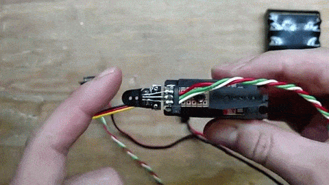
He’s been designing his own Real Time Motion Control System and Mini Servo board, or RTMCS2 for short and shown off a short video of it in action. By adding a force feedback sensor to each servo, not only do they copy each other, but if you put a load on one, you’ll feel it on the others!
And for a more thorough explanation, he shows it off in more detail here:
Black magic! Seriously though, [Wolf Tronix] works with animatronics and has some really cool projects. You should check out his site!


The solution for distant romance!
Been there, done that with a pair UR5 robots. Fun times.
Only if the 98′ patent troll is defeated. Talk about a chilling effect!
great project!
this is absolutely awesome and very useful, i am going to have to try one of these as haptic feedback for rc planes.
i bet one could easily interface these with frsky controllers due to the modular wiring.
Frisky controllers! Just the thing for the telesex project mentioned above!
If those weights are from a triple beam balance then the weight stated on them is not normally their actual weight.
They have do have two numbers on them… I assume that the smaller number is the actual weight.
Thanks,
Wolf
This is for teledildonics… isn’t it?
Ah, that’s the word I was looking for.
For those wondering how it works:
The virtual spring is F=kx, where k is the spring constant, and x is the displacement from center.
Force from all the servo sensors are summed together and subtracted from the virtual spring force.
Then the micro solves F=ma, for acceleration (a), where F is the total system force, m is the system mass.
Acceleration is integrated to get velocity, and velocity is integrated to get position.
The position is then converted to the standard 1-2ms servo pulse.
The velocity term is also used to calculate a damping force, which also gets summed.
Also, the third article link should point to the RTMCS2:
http://wolftronix.com/rtmcs2/index.html
It currently points to the first version RTMCS which is 10+ years old. ;)
Thanks for posting,
Wolf
Executive summary: magic.
Magic = Physics ;)
Now you should create a Space Marine Power Fist (glove), feel that you are holding something and literally start crushing things.
:D
What force sensor is used?
This is the hall effect sensor I used:
http://www.digikey.com/product-detail/en/A1304ELHLX-T/620-1548-1-ND
I would like to know where you sourced those micro magnets?
Ebay, search:
1/16 x 1/32 neodymium magnets
Thank you!
Updated the link, sorry about hat!
I’m curious what are the sensors that you are using? Also, while your explanation is very nice, it would help to see a code snippet — is this available anywhere?
Sorry, didn’t see the link to the sensors.
awesome ..
will u open source the program??
Scaling this with programmable resistance could put Nautilus and every other dead-iron based exercise equipment maker out of business.
That’s a nice idea: have some form of load-cell attached (like the spring/magnet combo here) to a motor-controller motion rig and simply stop the rig from moving until a certain level of force is seen. As long as the motor/slide arrangement can handle the back-driven forces then you could program it to any amount of ‘virtual weight’.
Yes! I’ve been waiting for this information for a little while now! This is pretty darn awesome, I love how you’ve implemented the force sensors.
I do see that the rubber mounted servo has a little bit of hysteresis to it.
The current in the motor itself is actually representative of torque, I wonder if this same effect could be achieved by measuring motor current and using that as your force signal. I’ll have to break out a servo and give it a try.
Hysteresis is always a problem with force sensors. It can be mapped and removed in software, (hysteresis will be proportional to peak force).
You can use the current thru the motor, but it will never be as sensitive as a force sensor at the end effector.
Imagine back driving an unpowered servo, the force this takes would be the minimum you could sense with the motor current.
Hope that helps,
Wolf
Oh I don’t have to imagine, I have a servo in my paw right now. :p
I only brought it up because it could be a cheaper, if cruder, method of force sensing for certain applications.
For doing it right though I suppose there really is no better way than to watch displacement on a spring element.
I might just give the current feedback method a try though, who knows, it might be useful somewhere.
Thanks for the reply, I like what you do and hope to see more!
Impressive results! I think this would be a perfect application for a 3D printed servo mount. You could integrate a flexure into the structure and center it’s flex axis on the servo output shaft. (and integrate a mounting for the hall-sensor PCB)
Yup… But I would need to make/buy a 3D printer. ;)
One interesting thing I noticed when using the case as the sensor.
If you crank the sensor gain up. The force sensor will pick up the torque from the rotational inertia of the servo motor changing directions.
This can cause the system to self oscillate.
Not only awesome as a project, but also uniformly the most positive I’ve seen HaD be for a while.
Really, really cool! I’m going to nab some of these sensors next time I do a digikey run.
Also, wolf: some of the video links on your site appear dead (bottom of this page: http://www.wolftronix.com/tail/index.html ). I have a friend who’s super in to tails, but the archive.org link is pretty slow: http://web.archive.org/web/20060228223941/http://www.wolftronix.com/videos/PA010005.MOV Any chance there’s a youtube version or something a bit faster I can send him?
Sorry about that, large parts of the website have been lost over the years, (due to hard drive crashes, back when I ran the webserver).
Here is a good video:
http://youtu.be/xR8i9-gIncs
That is actually me wearing a tail, 13-14 years ago. ;)
Old school hackaday post on the tail:
http://hackaday.com/2009/09/09/life-size-animatronic-wolf-tail/
More recent stuff:
http://www.youtube.com/playlist?list=PLQdu_G7xyFIQTkVES0KELgHnIPn9v5AxK
Yiff in hell!
Awesome thanks!
Another question: where did you get those magnets? Especially the suuuuper tiny ones you press-fit into the servo horn?
Answered further up in the comments – Ebay search “1/16 x 1/32 neodymium magnets”. I have some, they’re inexpensive and have come in handy for a multitude of purposes, and recommend having them around whether you intend to build strain gauges or not. My favorite use, epoxy them to one end of PCB standoffs, and you have boards that snap onto any ferrous surface. I never considered they could be used for DIY strain gauges too, until seeing [Wolf]’s project.
Awsome work man!
Reminds me of playing with selsyns … one of my favorite older technologies.
Hey it reminds me of vimphin ;) (shameless plug)
http://hackaday.com/2012/05/31/robot-arm-provides-haptic-feedback-from-the-virtual-world/
. . . . wouldnt this be kinda useful in an exoskeleton of some sort?
Am I the only one wondering what sensor is he using? Anyone has a clue?
See above! http://www.digikey.com/product-detail/en/A1304ELHLX-T/620-1548-1-ND
I’m glad you submitted this, a really nice hack, and hopefully you’ll inspire others, who will inspire you.
Force Servo project: http://myresearch.company/f-servo.phtml
Hi there, i am a bit confused when you put the hall sensor align in a fix position with the magnet (as i understand, force measurement can only occur whenever the resistance being affected by the magnetic flux change) and how the motor is able to move along the load by doing so. I would be very appreciated if you can enlighten me, thank you.