If you work on RF circuits–even if you aren’t a ham radio operator–you ought to have a dummy load. A dummy load is a non-radiative “antenna” with known impedance that you can use to test your RF circuit without radiating. For radio work, you usually just need a 50-ohm resistor that is non-inductive (at least at the frequencies you are interested in) and that can dissipate the amount of power you’ll expect it to handle (at least for a short time). [VO1PWF] wanted a dummy load and built his own.
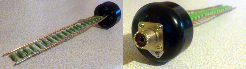
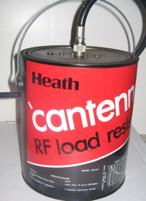 The Cantenna (not the Pringle’s kind; see right) was a famous dummy load design when Heathkit was in business. It was a single carbon rod immersed in a paint can full transformer oil (which we now know was full of dangerous PCBs; and we don’t mean printed circuit boards). [VO1PWF’s] design is a little more practical, using some resistors in parallel (20 1K resistors), a plastic pipe housing, and mineral oil to keep it all cool.
The reason for the parallel resistors is to maximize the power handling capability. The resistors are 3W units, so the dummy load–in theory–can handle 60 watts. Often, high power resistors are wire wound and thus have a good bit of parasitic inductance that makes the dummy load reactive (not a good thing since that makes the load impedance vary by frequency). They do make non-inductive wire wound resistors, but these aren’t truly non-inductive. The wire winds in two different directions, so the inductance tends to cancel out. We wouldn’t trust them to be a pure resistance in a high-power dummy load design.
There were three things we noticed about the project, though. We’d have matched the resistors since even a small difference in value (or even a little difference in the solder joints) will cause the lowest value resistor to take much more current than the others. For example, if all the resistors were actually 1K except for one that was 5% low (950 ohms), the low resistor will dissipate almost 3.15 watts.
The situation gets worse if the rest were all 5% high, and this is a typical situation since many manufacturers sort out precise values for higher tolerances; in a batch of 5% resistors, none are likely to be within 1% of the nominal value because if they were, they’d have been marked as 1% resistors. Increase the spread (with 10% resistors, for example) and it gets even worse. In practice, you’d probably want to derate the resistors so that by design they stay well below their maximum design power to make the circuit more forgiving of tolerance and differences in wiring. Also, for short durations, it isn’t like the resistors will explode if they slightly exceed their power ratings. However, it probably isn’t wise to try to run the full 60W into this load for any length of time.
The solder job was neat and fairly short. That’s the second thing we noticed: over a Cantenna, the wiring is going to add parasitic reactance and make the dummy load less useful at some high frequency. It would be interesting to know where that frequency is. The bus wire is pretty thick, but using something even larger (like the PCB material in the video below) might increase the useful frequency.
The final thing we wondered about was using ABS for the case. Even with a Cantenna, there are famous stories about operators working DX (long distance) while accidentally hooked to a dummy load and nonetheless getting through. And the Cantenna was in a metal case. We expect that a dummy load in PVC would radiate a lot more. And while this is still better than using an antenna, and electrically this isn’t a problem, we’d love to see some test measurements of the radiated power.
We see quite a few dummy loads that are programmable loads for LED drivers, for example. However, we don’t see many high-power noninductive loads suitable for use with a radio. The video below shows a similar design with a metal can and thicker bus bars that is closer to the old Heathkit design, although it still uses multiple resistors.
Cantenna photo: By [Gerry Ashton]. CC-BY-SA-3.0 via Wikimedia Commons


Carbon composition is usually best for this but they are hard to find in tight tolerance. Matching values and short leads are a must. A ladder arrangement as shown will have increasing inductance for resistors further from the termination. A radial arrangement may work better.
I would argue metal film is better for this application, but definitely not wire wound resistors as used here.
I agree. Carbon resistors generally have poor resistivity – temperature coefficients, high thermal noise, and high 1/f noise.
Thermal noise is independent of topology; it just needs to be a resistance.
Correct. As the resistance increases due to the larger temperature coefficient, the Johnson-Nyquist noise increases.
Most metal film resistors are spiral-wound.
I think you mean most wire wound resistors are wire wound. The winding can be done with wire of round, square, flat ribbon, or any other cross-section. Metal film resistors are vapor deposited, or are wide, flat sheets of metal formed into a cylinder, or simply cylindrical tubes of metal with connections at the ends.
Or simply a flat sheet of vapor deposited metal for surface mount parts.
That’s still called a wire wound resistor Annie. The distinction is the winding, or spiral cut in the conductor in this case, acts like an inductor, which is undesirable in this application.
Large (>5W) wire wound power resistors are not made that way.
Maybe a foil resistor would be the best for this use.
Can’t one just compensate for inductance of wire-wound resistors by adding a switch with capacitors selected for different bands to match impedances?
Not in this application. The ideal dummy load is a purely resistive load with a reactance that does not change with frequency.
Depending on what the individual resistors cost / what you have available already, one could also get a single RF power resistor — I have one of these laying around waiting for me to build up an appropriate heatsink for it. https://www.digikey.com/product-detail/en/CHF9838CBF500L/CHF9838CBF500L-ND/3741064
Modern day PC CPU heatsink (air or water cooled) can easily take 100+W or so. I wonder if 2 of them – one on the back side and one on the front side with some metal shims could make a 200W RF load.
Thanks for the tip. I will definitely use this the next time I need an RF load. Just have to heatsink and terminate.
I didn’t know that those existed, thanks for the heads up!
These are the right kind of resistor to build a dummy load for radio frequency, unless the ceramic coated wirewound ones seen in the video. Just beware that those high frequency resistors contain beryllium oxide which can be dangerous if in powder form (beware of sanding!).
beryllium = pink in colour?
or can it be dyed (any) color ?
Those are nice. Thanks for the link.
Am I the only person why measures resistors and labels them with their “real” resistance, instead of the ball park figure that is the colour code.
shut up! you are fooling my work flow in labelling all my 0402 and 0603 resistors…
I have a 100W rated dummy load acquired from the cellular industry that is supposed to be a pure 50Ω load anywhere between 1 and 3000 MHz.
I once swapped between it and my regular 6-meter antenna during a net on a local repeater, and no one could tell the difference. I was only using 5 watts at the time. Needless to say, I only use it when necessary.
I would rather suspect you had a real cruddy cable / switch, Remember that cheap coaxial cables can have shielding coefficients of as low as 35%. and switches especially the average ham type switch can have poor isolation as low as 15-20db. The true test would have been hardline cables between the rig and the rest, a real coaxial relay with an isolation greater than 80db at the frequency you are running and then the load. I trust the load a lot more than the rest of your station especially if it came from the cell phone industry. Chances are that load cost as much as your radio if you buy it new. I am using commercial broadband loads / attenuators and some of them cost 3-4k if bought in single quantities.
Making is always good, but I’ve bought real 100 W loads off ebay for $60. Someone had a bunch of mill-spec Bird loads at the time. Sometimes a little patience pays off.
I don’t know where you get the idea that the Cantenna was a carbon rod or filled with toxic oil. I actually built one and it was a series-parallel collection of ordinary carbon resistors submerged in mineral oil.
The Heathkit Cantenna was sold without cooling oil. Adding cooling oil was the user’s responsibility. Some people used medical grade mineral oil, others used transformer oil with PCBs. If you purchased one of these used with oil, it is best to assume it is toxic until proven otherwise.
I had one. The instructions said to use mineral oil. There were, should we say, “hackers” who “improved” the performance by using toxic transformer oils, but this was not what Heathkit instructed.
I built one that was as i described.
somewhere i heard that transmitting with anything connected could cause you to burn up the rf section of the transmitter.
but what would happen if you tested and radiated?
and is this allow a non licensed builder to build a transmitter so a licensed operator can transmit?
This allows you to run the transmitter without radiating RF. It turns all (hopefully) of the RF power into heat. So, with this attached, you can run the transmitter without a license.
If the amplifier runs with nothing connected, or if the load (or antenna) you have attached to the transmitter is not impedance matched properly, then the RF back-reflection can burn out the amplifier stage of the transmitter.
so even short bursts of transmitting like as if you just clicked the talk button for a couple seconds at a time can cause enough interference that it would be illegal?
In the US- Yes. But I don’t think anyone would notice.
You can attenuate the transmitter signal enough to be legal, so that the signal will be lower than the radiated power that needs a license, so you could still pick up the signal a short distance away.
Another reason to use a dummy load is that while developing a transmitter or amplifier, it’s output specifications may not be within legal limits for spurious outputs. If you are using a dummy load instead of an antenna, you won’t be radiating all the extra (illegal) stuff.
All the dummy loads I have seen use a radial design. The one pictured will have a wave reflection – or – at a specific frequency it would have a standing wave which means it will much higher then the DC resistance.
Also the so called ‘non-inductive’ wire wound resistors aren’t wound both ways – they are bifilar wound. I have also found that some ‘normal’ wire wound resistors are also bifilar when I have pulled them apart to use the nichrome (nickel chromium) wire for a cutter.
Exactly. The one in the video has the best arrangement (resistors sandwiched between two PCBs) but still uses the wrong kind of resistors, they’re wirewound, ie inductors: totally inadequate for radio frequency above a few megahertz.
The standing wave issue for the load shown would not get severe until you get above 100MHz or so. I think anything under 1/10th of a wavelength is negligable.
Yeah you need a good dummy load but I would recommend a good calibrated one with a heatsink that won’t drift crazy
In addition to the shielding deficiencies, the PVC container will not conduct heat off of the oil very well either. A metal can will radiate the heat better, allowing you to run the load for a longer time before everything is too hot. Better still would be something with fins.
The way broadcast engineers handle such things…
http://www.aliexpress.com/item/Free-shipping-resistor-RFP-TC-250-50-50-TC-RFP250-RFP-250-50-250-50-TC/32237954281.html?spm=2114.01020208.3.205.D68UmA&ws_ab_test=searchweb201556_4,searchweb201644_4_79_78_77_82_80_62_81,searchweb201560_4
Hooked series-paralell four of them should be good for up to a KW. Don’t forget to use distilled water as coolant bath.
Doc
Be careful, this type of component is very often faked (they can cost tens of dollars for one, so it pays off). You may want to test it first with a DC power supply before blowing up an expensive RF output stage.
as most of my measuring equipment does not handle high power well, and use bnc connectors i simply use old thinwire terminations from some former computer manufacturer. i didnt check radiated power, as even coax cable tends to be not 100% radiation free. nothing is perfect :)
I don’t suppose mounting the resistors in opposite directions would help? And it beats a lightbulb.
lightbulbs were commonly used as they had 100W rating aswell (the most common ones, now baaaaaaad!!!) for transmitters with tube technology, output transformers and 600 ohm dipoles connected via “chicken ladder” twinline. the output stages were “tunable” to various impedances, so it didnt matter… you could aswell use a piece of coal. at shortwave frequencies nothing to worry about
I use car headlamp bulbs for low voltage DC dummy loads, but they have a huge inrush current when the filament is cold. The Inrush can be 15 or 20 amps, while the operating current is about 4.6A. A lightbulb has the advantage of operating as a load down to 0V, while electronic loads usually don’t start loading until some voltage above 0V (around 0.3 to 0.5V for the nits that I have).
This is an extremely useful article, and so is the accompanying discussion. A couple of observations:
–the successor to the Heath Cantenna lives on. It’s available from MFJ in Starksville, MS, USA.
–back in the day, we did use lightbulbs. Large ones in the 250-500 watt industrial style with Mogul bases, not the familiar home sockets called Edison bases. They did radiate bit but not much more than the Cantenna. The were good restive loads and the built in power meter (brightness) was helpful for tuning.
–it’s always a good idea to bring the power up slowly when testing on a dummy load.
–in general, use a dummy load MUCH larger than the power level under test.
thanks NY2RF
I go more primitive and make the resistors out of thick pencil leads ( graphite ) then use alligator clips in the ends , multi meter to get 500 ohms and connect 10 of them. then submerse in oil , no one can argue there is inductance here .
For the low price of $34.95 this one can’t be beat.
I use mine all the time.
Handles 100 watts good to 144 MHz
http://www.ohr.com/rfl100.htm
Perhaps Modern day MFR resistors are not spiral type byt they manage to handle the deposition thickness and later file it to get the needed value. Thus we may not call them wire wound.
If agreed we can call metal deposition like former times carbon deposition resistors, LoL.
I strongly feel that we can also get non -inductive wirewound resistors now a days, howowever their effectiveness could be.
A good Project for persons like me,
Thanks for the metal can dummy load, Al Williums.
Best of 2016
regards sarma VU3ZMV
As a broadcast engineer I had occasion to repair two 50KW comercial water cooled loads. (Burnt one up myself by forgetting to turn on coolant pumps before running a 22KW TV transmitter into it…. Made PLASMA! before transmitter SWR protection kicked it off!) But was rather surprised to find that they both consisted of a 200W metal film 50 ohm power resistor surrounded by the water jacket. Only trick was they had to be supplied with non-conductive coolant. (Distilled water / antifreeze).
Doc
If I needed something like this at high power, I’d keep an eye on the bay for some NOS or surplus Cesiwid Carborundum resistors. Non inductive, precise and they can handle high power. Expensive and hard to come by new if you don’t know where to look. Those are what you’ll find in actual purpose built professional dummy loads.
I built one of these and hooked up an analyzer to display the reactance at frequencies from 1.8MHz to 28MHz. http://www.hamradioqrp.com/2016/02/resistance-is-not-futile.html
I would like to build a dummy load that will handle 250W.
Can you build it or send me a design and part list to build?
The idea was to match a typical 50w mobile rig, I designed the dummy load for above that wattage to make sure nothing was stressed to its max. I have used it on 3.7-148 Mhz without issues. PVC was the cheapest and readily available container to use at the time (living on an island in the north atlantic does not give you many options for projects and often ideal items are too hard to come by…too costly….and shipping is always a problem in newfoundland). I could have used it without mineral oil. But that would lessen the lifespan of the resistors. I did test radiation using a field RF meter. I went from 1.8-144 and all the bands in between. No issues were present on all bands except 6M which at 50w gave a very slight rf signal, but nothing to worry about. Like anything in the hobby tell 10 people to do the same project you will get 10 results and 10 different ways of construction. Depending on your construction and resistors chosen you may have different results. The best thing about it is you get to do some home brewing, learn, and if things do not work out you may be out $10 which is nothing major…best to all, 73’s from newfoundland…de VO1PWF