
Sorting. It’s a classic problem that’s been studied for decades, and it’s a great first step towards “thinking algorithmically.” Over the years, a handful of sorting algorithms have emerged, each characterizable by it’s asymptotic order, a measure of how much longer an algorithm takes as the problem size gets bigger. While all sorting algorithms take longer to complete the more elements that must be sorted, some are slower than others.
For a sorter like bubble sort, the time grows quadradically longer for a linear increase in the number of inputs; it’s of order O(N²).With a faster sorter like merge-sort, which is O(N*log(N)), the time required grows far less quickly as the problem size gets bigger. Since sorting is a bit old-hat among many folks here, and since O(N*log(N)) seems to be the generally-accepted baseline for top speed with a single core, I thought I’d pop the question: can we go faster?
In short — yes, we can! In fact, I’ll claim that we can sort in linear time, i.e a running time of O(N). There’s a catch, though: to achieve linear time, we’ll need to build some custom hardware to help us out. In this post, I’ll unfold the problem of sorting in parallel, and then I”ll take us through a linear-time solution that we can synthesize at home on an FPGA.
Need to cut to the chase? Check out the full solution implemented in SystemVerilog on GitHub. I’ve wrapped it inside an SPI communication layer so that we can play with it using an everyday microcontroller.
To understand how it works, join us as we embark on an adventure in designing algorithms for hardware. If you’re used to thinking of programming in a stepwise fashion for a CPU, it’s time to get out your thinking cap!
A Parallel Approach
Our goal is to deliver a module of digital logic that receives its data serially, or, once per clock cycle, and sorts that data. To achieve a linear-time benchmark, I’ve opted for sorting the data while it’s being clocked in. In that sense, once we’ve finished clocking in our data, our array should be sorted immediately afterwards, ready to be clocked out again.
If we can construct such a block, then our hardware solution is linear, or O(N). The problem might seem complicated, but the solution is actually rather simple — provided that we’re doing our sorting in parallel. To unpack how this algorithm works, let’s look at a simple case: sorting a three-element array.
Example Time: the Three-Sorter
Let’s start with a quick example of sorting a three-element array into a container of size three.
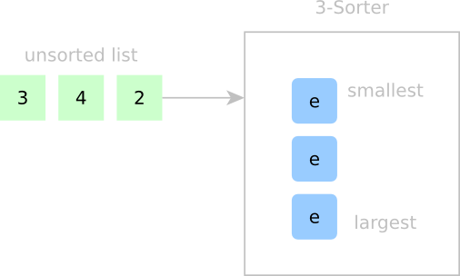
On the left we’ve got our unsorted list ready to be clocked in serially; on the right, our “Three-Sorter” sorting unit with a cell array of size three. (An e indicates that the cell is empty.) Inside the Three-Sorter, I’ll declare that elements in this cell array from top-to-bottom are stored in increasing size. Our goal is to put each new element in the right spot based on what’s currently inside the cell array. At this point, we don’t actually know any details about the signals that will make this sorting happen, but we’ll walk through the flow of data and build up that logic afterwards.
Sorting Step 1:

In Step 1, all cells are empty. We start by inserting a new element, but we need a place to put it. Since all cells are empty, this new element is the smallest we’ve seen so far, so let’s insert it at the top. Even though there’s just one element, I’ll make a bold claim that our cell array is sorted.
Sorting Step 2:
In Step 2, we try to insert the second element. Our first question might be: where does this element fit in the current container? Looking at all the cells, we can see that this second element 4 is greater than the elements in all other occupied cells. 4 fits into any of the empty slots after 3, but we’ll put it in the first empty slot after the last occupied slot. Hence, our new array is still sorted.
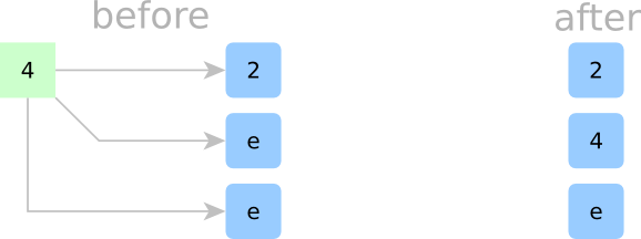
Sorting Step 3:

In Step 3, we’ll insert the third element, 3. Looking at our container of cells, we know that 3 fits nicely between 2 and 4, but there’s simply no empty space. To make room, we’ll kick 4 downwards into the next cell and put 3 in 4‘s old spot. (Sorry, 4, but it’s for science!) Now that we’ve inserted 3 — guess what — our internal cells are still sorted!
Taking a step back, every time we insert a new element, we look at each cell and ask ourselves: “Does my new data fit here?” Because we’ve agreed beforehand that the contents of our cell array will always be sorted, it turns out that every cell can answer this question independently without knowing the contents of the rest of the cells. All it needs to do is ask for a few bits of information from the cell above it.
Alas, if only these cells were “intelligent” enough to act on their own and ask questions about their data and their neighbor’s data. If they could, then I claim that all cells could independently agree on who gets to hold the new element as each element gets clocked in.
Signals for Parallel Sorting
Now that we’ve seen cell-sorting in action, let’s revisit this example while we take a deeper look at how these cells communicate. Without knowing the contents of the rest of the cells, all cells need to independently agree where the new element goes so that our new element gets stored once and only once. Let’s see this “cell-talk” in action.
Detailed Sorting Step 1:
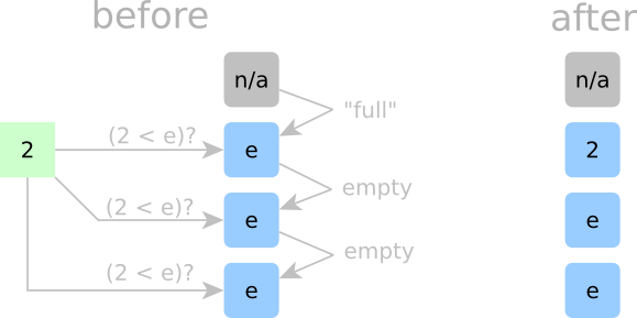
In Step 1, we start by inserting 2. Here, all cells are empty, so any spot would be fair game. Since 2 is the smallest element we’ve seen so far, it needs to go in the top cell. The top cell also needs a way to tell all other cells that it just got dibs on the incoming 2. We don’t want to have a “cell-claimed” signal that propagates all the way down the chain; that’s just too slow. Rather, we’ll make a deal across all cells. If a cell is empty, it will only claim the incoming element if its above neighboring cell is occupied. Now, when new data arrives, each empty cell just needs to look above at the cell on top of it to see if that cell is occupied. If it is, that empty cell claims the new data. If it isn’t, then we’ll assume that some empty cell above it already has dibs. To bootstrap the first cell into always claiming the first element of an incoming array, we’ll hard wire it’s “above-cell-is-occupied” signal to True. (That’s the fake grey cell in the diagram above.)
This “deal” we just made needs to be so strict that we’ll call it “Rule Number 1.”
- Rule No. 1: if a cell is empty, it will only claim the incoming element if the above cell is not empty.
Detailed Sorting Step 2:

In Step 2, a second element, 4, arrives to be sorted. Here, we know that 4 should go after 2, but how do our cells know? If a cell is occupied, it needs to ask the question: “is this incoming new number less than my current number?” If it is, then that cell will kick out its current number and replace it with the new number. That current number can get kicked down to the next cell below it. Hmm, if every occupied cell asks that same question, then there could be multiple cells that would be more than happy to replace their current number with the new number. If that were true, then we risk storing multiple copies of an input element. Well, we can’t have that, so we’ll make another rule.
- Rule No. 2: If a cell is occupied, it will claim the incoming element if both the incoming element is less than the stored element AND the occupied cell above this cell is not kicking out its element.
Phew! Now only one copy of the incoming element will be stored in the entire cell array.
To make sure that we aren’t losing data when cells kick out their data, we’ll make another rule.
- Rule No. 3: If the cell above the current cell kicks out it’s stored element, then the current cell MUST claim the above cell’s element, regardless of whether or not the current cell is empty or occupied.
If a cell is empty — phew — it’ll just follow “Rule Number 1” and “Rule Number 3.”
Detailed Sorting Step 3:
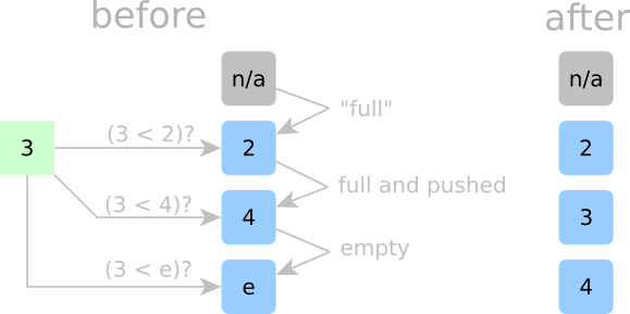
Now, let’s try to insert a 3 as in the last example. 3 should fit nicely in 4‘s spot, but how do our cells know? The top cell is holding a 2, and since two is less than three, the 2 stays put. The second cell, however, is holding a 4, and since three is less than four, 4 gets the boot and needs to go down a cell. The first empty cell could take the new data since it’s empty, but since 4 just got kicked out from the cell above, this empty cell gets the 4 instead. All other empty cells below follow “Rule Number 1”. Each of these cells is empty and each cell above these cells was also empty at the time, so they stay empty.
We’ll make one last rule for cells that claim new data:
- Rule No. 4: If a cell is occupied and accepts a new element (either from the above cell or from the incoming data), it must kick out its current element.
With all our other rules, we can guarantee that any element that gets kicked out will be caught by the cell below.
If all of our cells follow these rules, then we can guarantee that, together, they can sort arrays without needing to know about the cell contents of all other cells, because it is implicit to the cell array structure. And with that said, each sorting step is fast, bubbling down to N identical and independent questions asked in parallel at every clock cycle.
Behold–a Sorting Cell
Now that we’ve ironed out the rules, let’s look at the anatomy of a single sorting cell, each of which makes up a unit in our cell array.
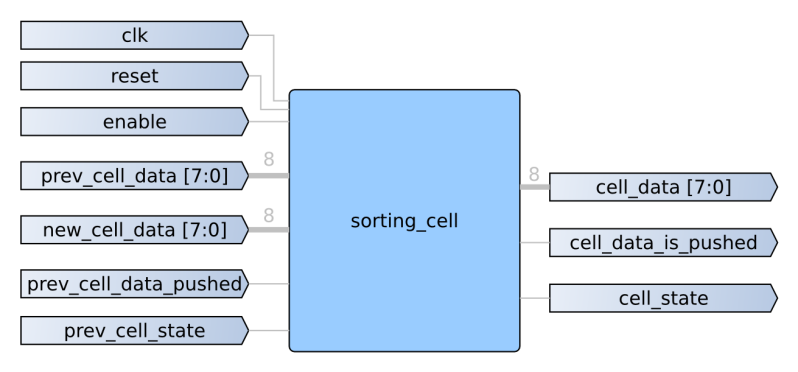
To follow the rules we just generated, each cell needs to know information about it’s upstream cell and pass along information about it’s current state and data. In a nutshell, these signals just become inputs and outputs to a collection of internal digital logic. To “follow the rules” of our architecture, we’ll need to resort to a small snippet of sequential and combinational logic.
First, each cell needs to keep track of its own state, empty or occupied. In SystemVerilog, we can implement this feature as a two-state state machine. To make determine whether or not we’ll claim the new data, previous data, or hold on to our current data, we’ll need to follow the rules, which I’ve wrapped up as one block of combinational logic.
First, we’ll need some intermediate signals:
assign new_data_fits = (new_data < cell_data) || (cell_state == EMPTY);
assign cell_data_is_pushed = new_data_fits & (cell_state == OCCUPIED);
new_data_fits is simply our criteria for whether or not a cell can accommodate new data.
cell_data_is_pushed tells us whether or not the current cell data in an occupied cell is getting kicked out to the lower level.
Now, we can put together the true nuts and bolts of our sorting cell: the logic for determining what data gets stored.
if (reset)
    begin
        cell_data <= 'b0; // actual reset value is irrelevant since cell is empty
    end
    else if (enable)
    begin
//{shift_up, new_data_fits, prev_cell_data_pushed, cell_state, prev_cell_state}
        casez (priority_vector)
            'b0?1??: cell_data <= prev_cell_data;
            'b0101?: cell_data <= new_data;
            'b0?001: cell_data <= new_data;
            'b1????: cell_data <= next_cell_data;
        default: cell_data <= cell_data;
        endcase
    end
    else
    begin
        cell_data <= cell_data;
    end
The block above is a Verilog case statement with “don’t cares” making some signals take priority over others. The first case is just “Rule Number 3” where a cell always takes the previous cell’s contents if that number is kicked out. The second case is for a cell that is currently occupied, but satisfies the “strictly-less-than” criteria. The third case is for storing the biggest element yet in the first empty cell, or “Rule Number 1” with “Rule Number 3.” The final case isn’t part of the algorithm, but it’s for shifting our data back up the chain when we want to retrieve our array of sorted elements.
Perfect! Now that our sorting cells are encoded to follow the rules, we simply create an array of these with a Verilog generate statement, and our linear-time sorter is complete! Now, give it a go by uploading the source code to real FPGA hardware.
Getting Edgy with Edge Cases
Before celebrating, it’s worth bringing up some edge cases. What happens if our unsorted array has repeats? Can we sort fewer elements than the maximum capacity of our hardware sorter? Without transforming this post into a novel, I’ll reassure you that this solution does indeed handle repeats and also sorts arrays from size 0 up to N, where N is the total number of sorting cells that we’ve synthesized onto our FPGA. It can’t however, swap back and forth between sorting arrays of signed or unsigned data types without tweaking a few parameters in the source code first. All that said, I encourage you: be skeptical! Don’t believe me until you worked these edge cases out for yourself on paper or in simulation.
Trading Time for Space
We did it! We’ve built our very own sorting peripheral in hardware that chews through unsorted arrays and sorts them in linear time! But, as with all too-good-to-be-true scenarios, we’ve paid a hefty price in FPGA resources. While we may have an ultra-fast sorter built in hardware, I can only instantiate sorting hardware to sort 8-bit arrays up to ~1000 elements long before I’ve exhausted my FPGA’s resources. We’ve traded time for FPGA macrocells. Luckily, the amount of hardware grows linearly as we increase the number of sorting cells to sort larger arrays.
Putting on your “Algorithms-in-Hardware” Hat
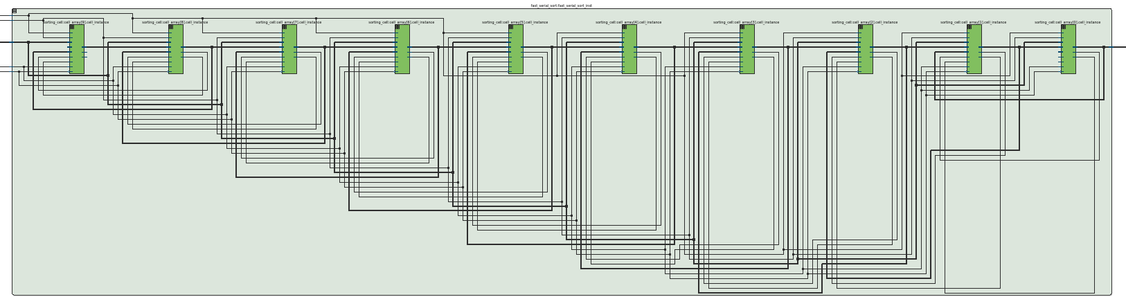
I snagged the image above from Atera’s RTL Viewer after synthesizing a Ten-Sorter, and something is strange. As I grow the size of the sorting hardware or change the data type from 8-bit to 16-bit to 32-bit integer by tweaking some top-level parameters, I lose the ability to see all of the connections and signals passing back and forth in my head. It’s just too complicated. There are too many wires.
Nevertheless, the design itself bubbles down to a very simple unit, the sorting cell, that repeats itself many times over with each repeat performing the exact same task. Because we know the behavior of each of these sorting cells, we can predict the behavior of an entire system made up from these blocks — even if we can’t visualize all of the connections in our heads! This type of procedurally generated complexity strikes me as very beautiful, the same kind of beauty that we’d find in fractals or recursive algorithms. If you’ve made it this far, thanks for joining me, and keep us all posted on your adventures in the world of “algorithms in hardware.”


The first programing course I took was in 1968 in high school working with a language called FOCAL on a PDP-8 that the school had acquired on loan. The instructor was adamant that we learn to program several sorting routines saying that if we went on to be programmers, these would be our bread and butter.
Was the instructor correct?
I went on to become a chemist and metallurgist didn’t do any serious programing until I started working with spreadsheets on PCs, so no. The topic dredged up this old memory though and reminded me that those that had spent their time in the unit record world of data processing had no idea what was coming down the pike.
Programming is one of those interesting anti-inductive fields where the one thing you can really be sure of is that if doing X manually is the “bread and butter” of today, then it’ll be the library function of tomorrow and the language feature of the day after.
Nice solution.
I have thought for a long time that there are a lot of things we do to data with a CPU that would be massively faster if the ram chips could do some basic parallel operations. Although I don’t think you could get ram chips to be as programmable as an FPGA.
You mean like SSE?
SSE is more an x86 thing.
What I think he means is more like a CPU architecture that combined CPU logic block configs and data as in input stream instead of an instruction and data that is used in normal RISC CISC architectures. Except he is expanding into RAM decode and data logic. This is a doable thing in modern FPGA that has a lot of BRAM.
I looked for the wiki that explains this CPU architecture but I can’t recall it’s name.
Found it –
https://en.wikipedia.org/wiki/Application-specific_instruction_set_processor
Hmm,
Verilog … It’s an American thing.
Shields pop-corn with coat.
Do people outside the USA use VHDL?
Not being sarcastic, actually curious
No idea, but reasonably sure the whole thing is an inside joke among FPGA guys. Any FPGA/EE person worth their salt can do both VHDL and Verilog (or sV).
The reason they have to do both is that all the old Intellectual Property that ends up in projects is in Verilog but it’s too risky to send Verilog to an ASIC fab house unless you’re a GOD of Verilog! – where a F.Up can cost hundreds of thousands. So they have to know Verilog to understand the IP properly and VHDL for the final production.
The rest of the world doesn’t have that problem so they go straight to VHDL. And it’s not just an ASIC thing. VHDL can be used for a much broader range of technologies than Verilog or System Verilog.
Verilog is good for CPLD / FPGA but don’t trust it past that. An even this will probably change.
When I was deciding which to choose between Verilog and VHDL is tried both in a very limited way because I had no experience at that stage.
Verilog can “feel” more comfortable at first because it’s “looks” more like a programming language. The problem is that this only leads to confusion because any HDL is *NOT* anything like a programming language in any form of the expression.
Then I tried VHDL. I found the syntax heavy strict and cumbersome but after getting through some basics, I found that I could easily imaging what my code meant at a gate / register level. I didn’t have that same experience with Verilog. With verilog it’s hard to understand *exactly* how your code will be interpreted.
Ok, I’m off to cook some popcorn for the onslaught that I have just invited lol.
Funny. I started in Verilog, with a background in CS, and I never considered it like a programming language. When I type ‘if’, I see a mux.
@[Artenz]
Have you done VHDL?
It may look and feel like a programming language to start with but obviously it isn’t.
Nothing can be more removed from sequential programming than parallel states.
It’s just that the “look and feel” that it may be like a programming language just add confusion *because* it is not!
No, I’ve never tried VHDL, even though I live in Europe :)
@[Artenz]
Ok, Your an ‘old hand’ at this. Fair enough. I think you should at least have a look at VHDL. And yes the syntax sucks.
I used to work in a Fab and its exactly backwards to what you stated.
Back then everything was signed off in Verilog due to Verilog being 5x faster when running the signoff test patterns. Before I left we had mostly transitioned to a STA signoff, but I never saw a line of VHDL in the office. A colleague did signoff one ASIC in VHDL and it was painful.
Today we’ve moved to systemverilog and this feels better, I have designed in many RTL’s, I used to use VHDL here but found the type castng cumbersome and it broke down above 32 bits at the time so I swapped back to Verilog, here I follow a minimalist philosophy when coding. Academia loves VHDL, but a bit driver is the US defense establishment mandates VHDL.
Everyone on the world uses VHDL! Oh except the US where they mostly use Verilog.
VHDL uses metric bits.
… which is odd b/c VHDL was developed by the US Dept of Defense: https://en.wikipedia.org/wiki/VHDL
I know some engineers from a *HUGE* UK-based company (can’t name unfortunately, but you will have come across them) who all use Verilog. They’re talented, too. It might have been your experience that Verilog isn’t widely used, but for me it has been the opposite!
I learned VHDL first and used that for a year or two, but mostly use Verilog now.
[RÖB] You are a functional puzzle wrapped up in a sequenced enigma compiled into a encrypted 555 timer mystery, encoded iinto an Allen-Bradley logic ladder. If you are my program adviser we shall have words good SIR!
Please look up “The Hound and Hare Fable.”
The time is linear, but the total number of comparisons is O(N^2). Is there a way to get the comparisons down to O(n log n)?
Why bother? They all happen in parallel, so theres no cost to performance.
Because of the cost in, you know, actual cost?
The cost isn’t only related to the number of comparisons. It is even possible that an FPGA solution with less comparisons will take more area.
Power. As the hardware scales, this will be applicable to larger and larger data sets, possibly implemented in custom silicon rather than programmable logic. If the number of comparisons can be reduced with no penalty in time and a reasonable penalty in area, the power drop can be a major thing. Picture a device with 2^20 cells. O(n^2) vs O(n log n) is 2^39 operations vs 2^24, a factor of 2^15 in total energy used for comparison, which would be a major part of the power involved.
Take a look at bitonic merge sort. It’s used in GPU sorting and requires O(n log(n)^2) comparators with a delay of O(log(n)^2),
thanks. Parallel algorithms are not my field.
Animated Sorting Algorithms
http://www.sorting-algorithms.com/
An alternative implementation for this was shown here: http://citeseerx.ist.psu.edu/viewdoc/download?doi=10.1.1.83.5786&rep=rep1&type=pdf
It’s built with a single element composed of a register and a comparator. N of them are stacked together to sort N data words. When you push data into the top of the stack, it gets partially sorted. Then when you pull it back out, it’s completely sorted. The good thing is it requires no global broadcast of data: everything is local between a stack element and its immediate neighbors (except for the global clock).
I actually built one of these in a VLSI class back in ’83. MOSIS built the chip and I hooked it to my C64. It worked, but it only had space for 20 numbers so it wasn’t that useful.
Excellent article HaD. Keep em comin
Thanks Vikas, I totally agree. Joshua put together an amazing read on this topic.
It’s nice to see people leaving comments when they like something ;-)
Other linear sorting methods are possible if you allow input to be restricted. In high school I was taught something called the Frequency Distribution Sort which is O(n). It works when the input is easily enumerable. For example, if you are sorting integers in a known range you can allocate one bucket for each possible value, tally the quantity of values in each bucket which takes O(n) time, and then output the results in O(n) time. This sort would not work for floating point numbers.
Asymptotic analysis usually is applied to solutions where the problem can grow in size arbitrarily. The Frequency Distribution sort is asymptotically O(n). However, by limiting the input size of the problem, I’m not sure it’s fair to say that the hardware solution is O(n) since you can’t sort 1M items or 1B items. That said, implementing algorithms in hardware is very challenging and very cool. It was an interesting read.
This is a neat solution, but you can achieve O(n) (well, O(wn) where w is your word size) on integers (and a few other data types) entirely in software. The secret is to use a non-comparative sorting algorithm like Radix sort, since you can’t beat O(n*log(n)) using comparisons.
Obviously, hardware will always blow a software solution out of the water, though
The hardware solution doesn’t scale well, though.
*this* solution doesn’t scale well. There are better ways of doing this that do.
Your algorithm is indeed linear time (as I understand it the achievement is the parallel comparisons), but I think you under-emphasized the time-memory tradeoff (or in FPGA terms, the time-fabric tradeoff). A 2*N-sorter will probably require more than double the fabric than an N-sorter. Can you follow up with some basic results for synthesizing different sized sorters (like 2, 4, 8, 16, 32, etc) or something that will give us an idea on how quickly the required space grows?
To clarify, you claim that space grows linearly because you have to linearly scale the sorting cells, but I am skeptical. Does it actually synthesize that way, or do the comparison connections grow non-linearly?
Not necessarily. The primary storage could just be fixed (bit) width and have an indexing hash table to add storage width only when needed.
This will go some way with modern tech but is still limited in how far it can scale. At least the scaling limits are predictable.
This is EXACTLY what I was thinking the entire time I was reading the article. Furthermore, seeing as the purpose of using the FPGA is to sort lists that would take too long in software (i.e., because there is a very large number of elements in the list), you would need to support very large list sizes in the FPGA. However, the FPGA is also not going to be able to sort huge list sizes because it would not have enough fabric (storage and interconnect) to accommodate huge list sizes. So the overhead of communicating to and from the FPGA won’t have a chance to be amortized since it won’t be able to hold a large enough dataset.
I’m guessing that modern FPGAs wouldn’t be able to fit this logic for lists of size greater than around 10k – 100k elements. So you might get some speedup at those levels, but anything beyond that will just not fit. Keep in mind that the sorting logic is NOT using space-efficient block RAMs in the FPGA to store the data, the idea presented above requires the data to be stored as logic.
You cannot sort faster than O(N log N).
There are lots of ways to cheat however. For example: Take M buckets, the number M equal to the number of possible input values. place each input into its own bucket (O (1) for each item), when the input is exhausted, just can all the M buckets and output everything you find. The scanning is O(1) as it doesn’t depend on the number of input items N. So processing N inputs into buckets is O(N) and outputting N items again is O(N) so the algorithm is O(N).
But for reasonably sized inputs the number of buckets required becomes enormous. With modern computers you might be able to handle 32-bit inputs, but more quickly becomes unreasonable in the amount of memory (buckets) you need.
Having the sorting machine have O(N) hardware units is cheating and does not lead to a practical solution. Even bubblesort in hardware sorts in linear time. Have N (number of input items) hardwareunits. Put each input item n in sorting-unit n (for n=1…N). Each sorting unit n does: if (item-in-sorting-unit n+1 is less then mine, swap!) . Do this for N clocks and voila! bubblesort in O(N)!
Having N processing units means you’re able to do O(N) processing steps in O(1) time.
So, if you have N units in your FPGA, get back to me when you can sort in better than O(log N). (even the log (N) is tricky if you have to IO the data…)
“Having the sorting machine have O(N) hardware units is cheating”
I have to agree. It’s a neat implementation of something on an FPGA, but it’s not O(N), because the resources depend on the data.
I mean, on an FPGA, it’s not even the fastest you could do. You could just do it O(1), by making the entire logic asynchronous. It’d be awful, and the timing would be way lower than this implementation, but hey, it’s still O(1) by this same logic! I mean, for small N it’s probably even most efficient this way if you use DSPs, for instance. Resource usage grows faster than O(N), but again, still O(1)!
“You cannot sort faster than O(N log N).”
That’s correct for comparison-based sorting. It’s not correct for radix sorting, which is known to be O(N) with no extra space required.
It’s correct in the general case (ie. as performance on worst-case data) for all sorting algorithms, in my understanding. Radix sort only beats O(n*log(n)) if you’ve got a fair idea of the distribution of the data you’re sorting.
Practical radix sorts work by finding the exact distribution per-radix. In both theory and practice, they achieve O( (key_length)N ), for all distributions. Beyond asymptotic performance, radix sorts are typically a little quicker on e.g. already sorted data.
You can sort in O(zero) if you have a custom designed piece of hardware that just has all the input-to-output addresses to result in an sorted output for one specific input hardwired into it.
I think you mean to say “you cannot do a comparison-based sort with fewer than O(n log n) comparisons”. This statement is true (and the hardware in the article does O(n^2) comparisons); your statement is not.
Others have said it above. Algorithms are measured in two ways Time complexity AND space complexity. You sacrifice one to get improvements on the other but its somewhat of a zero sum venture. Space complexity is subject to physical limitations once hardware is built so time complexity is variable hence the extensive academic efforts to improve upon it.
A bubble sort implementation can be faster than quicksort for small N. This FPGA implementation is O(N) only for small N. I have a telephone book with 200,000 names. Please sort them with an FPGA and you’ll really find what O() you have.
I’m not entirely au fait with the CS behind O() but with this a sorted list is emitted every clock cycle. I.E. sorting 1 element takes 1 clock cycle, sorting 10 elements takes 10 clock cycles, sorting 200,000 elements takes 200,000 clock cycles, That is to say it scales linearly.
Of course that assumes you have enough cells. If you have 10 sorting cells then you can only sort lists of up to 10 elements.
O(N) notation means the time is bounded by a linear function of N. It might be N, or 1000N, or 100000000N, but as N goes to infinity it will approach some line. I don’t believe there is any FPGA big enough to contain 200,000 names on chip,which is required to combinationally compare a new entry to all existing entries. Imagine sending a list of 200,000 names, and all are already in order except that the very first name is supplied last. The FPGA must retain all input and not output anything just in case case the first entry on the list is received last.
OK, say there is an FPGA big enough to hold 200,000 names. What about 200M names? As some point there is a discontinuity where the FPGA simply fails. Even if you imagine a box full of FPGAs, at some point it fails. Even if you don’t care about the most extreme case, as N goes up, your cycle time drops, probably in the order of O(lgN), so you are still left with O(NlgN) time to sort the list.
But no computer is capable of sorting an arbitrarily large list. Even if you allow swapping to HDD there aren’t enough to for example sort a name for every star in the universe (or some other ridiculous task).
The bubble sort only works if you have enough memory to handle the list, this only works if you have enough cells. How does that effect the O of the function?
Well perhaps this method on a FPGA can reach a limit (Fail).
But a sorting algorithm running on a CPU is a state machine and state machines are very easily implemented in FPGA. If that’s not what you want then the while CPU can be implemented.
In any case, there is nothing a CPU based system can do that FPGA can’t. External RAM etc so the FPGA will always be capable of the most optimum solution.
RÖB, that is exactly the point. This is a good solution if you have a fixed number of things to sort and it all fits on chip. If I said I had an algorithm for sorting N things in O(1) time, just so long as N=1, you’d not accept that I really had such an algorithm. Computers can do radix sorts in O(N) time if you are willing to throw enough memory at it so that the buckets are asymptotically empty, but O(N) is no longer true for large N. That is the whole point of O() notation … what is the behavior as N grows unbounded. If you limit yourself to N=1 or N=10 or N=100 then you shouldn’t be using O() notation.
There are plenty of things that CPUs can do faster than FPGAs. Compare memory bandwidth, or do some floating point calculations, for example.
@[Artenz]
FPGA really has come a long way. What CPU did you think is better than FPGA and where do I download the HDV to run in in FPGA?
Or more to the point how can something be better than something else that can emulate it at (most likely) higher speeds?
Obviously I am excluding x86 / AMD here as this site is mostly about smaller CPU’s that are more easily emulated (simulated / synthesized).
Physical hardware limits are irrelevant to big-O notation. Just like there’s a list too big to sort on a given FPGA, there’s a list too big to sort in a given computer’s memory using quicksort. The asymptotic complexity is not affected by hardware limits.
Except the part where there are no FPGAs that can hold a phone book in registers.
The big issue I see is that O() is not usually meant to specify time directly, but rather complexity. This implementation isn’t really O(n) because there are far more than N comparisons happening, it just so happens if you through enough hardware at it you can do them all in parallel. Which is a neat trick to consider when your algorithm hits a wall on a standard CPU. It looks like the algorithm he implemented is in fact an Insertion Sort, which is actually O(n^2). So while it completes in n clocks, its still actually doing n^2 comparisons, thus O(n^2) complexity.
Big Oh notation can be applied to any function, it is just a means of specifying a bounding shape. In this case it seems pretty clear the author is discussing time. For CPUs, which historically do one op per cycle, or nowadays up to 4 ops per cycle or whatever, the number of operations is pretty directly correlated to time, so it is moot.
In any event, if N gets big enough, this FPGA sorter would need to break the large list into arbitrary chunks, sort each, and then we are reinventing polyphasic sorting algorithms, and there is no way to keep things linear in time at that point.
Actually, he’s not discussing time. He’s discussing *clock cycles*. Not time. On a CPU, those are the same thing, because the maximum clock is fixed.
For an FPGA design, the maximum frequency depends on the complexity of the design. Let’s just estimate: an N=3 sort could probably run at the maximum chip speed (~200-300 MHz). An N=1000 sort would probably run at more like 40-50 MHz.
Which just stresses this really isn’t an O(N) design in time. It’s an O(N) design in clocks.
@Pat – I thought the same too, that clock speed would drop off as fanout goes up.
However there is simple to work around. For a 1000 stage sort engine just distribute the data with three levels of registers, with an average fan-out of around 10, (e.g. maybe 8 at the higher level, 10 at the mid level, and 13 at the lowest level, to allow for longer, slower routes at the higher levels)
Clock speed doesn’t need to drop, as this avoids high-fanout nets. This only adds 88 register per bit of input (or about 0.1 register per bit per sorting cell, as the register is shared between 13 cells).
For this specific design, all of the sorting cells see the same input, so by definition the *input* is a net with fanout O(N). Can’t get around that. You can see that in the design, where the input goes to each cell.
Here’s a couple of enhancements that could be toyed with….
Rather than sorting in one 1024-cell machine, your could split it into four 256-cell machines, then merge the outputs of the four one the way out. Benefits – lower toggle rate (only 1/4th the cells will change in any clock cycle). You could even stop the clock to each 256-cell machine ticking until it is needed – nearly 1/4th the power, and 1/4th the fan-out on the inputs to the sorting cells (faster clock speed!).
Heck – if you have four engines, you could just clock in 4x as much data per cycle.. (not sure how the output side would work in that case – maybe do that in a faster clock domain).
Another option that you can use if you have four sorting engines is that you could route the incoming data at a sort engine based on the two least significant bits, avoiding the need to use registers to store those bits, and also removing the logic to compare those bits (saving power, space and routing, traded off against only being able to sort 1/4th the items if the least significant bits are the same). It could run in an “throw data at it until one engine is nearly full, read it all back, sort the next batch” sort of way.
Good old super linear speed up for parallel computing surface once again.
All sorting algorithms big O run-time is based on large collection of items using finite amount resources.
This sorting requires O(n) run-time and O(n) of memory. Bubble sort requires O(n^2) run-time and O(1) of memory.
If you send your serial data highest bit first you know the magnitude of the number as soon as you see the first 1 in the serial stream, then the number is in the right cell the moment the lest significant bit arrives. Right?
Don’t forget any quantum algorithms.
I would not expect that Quantum computing would lend itself very well to sorting algorithms. Classical computing seems more suitable.
This is not quite O(N) (which implies O(1) per insertion.) That’s like saying a ripple carry adder is O(1). As you add more sorting cells, the critical path increases. This is because the “push” signal needs to be propagated all the way from the first cell to the last cell.
However, you actually don’t need to propagate that signal! You can do this in O(1). Try implementing each sorting cell ONLY in terms of internal registers, registers from other cells, and internal combinational logic — NOT in terms of combinational logic outputs from other cells.
Instead of propagating the “prev_cell_data_pushed” signal, you can just look at the previous cell’s data. If the new data is less than the current AND previous data, you know the previous data will get pushed to you, so takes its value. If the new data is BETWEEN the current and previous data, take the new value. Otherwise, keep your current value. Something like this (may contain bugs):
if (reset)
begin
cell_state <= EMPTY;
end
else if (enable)
begin
if (cell_state == EMPTY) begin
if (prev_cell_state == OCCUPIED) begin
cell_data new_data) ? prev_cell_data : new_data;
cell_state new_data) begin
// This would be “prev_cell_data_pushed”,
// but is generated only in terms of data known at the start of the clock cycle,
// not as an output of a previous sorting cell!
cell_data new_data) begin
// new data fits snugly between the previous cell and this cell
cell_data <= new_data;
end
end
end
This means you can add more hardware and chain a bunch of these things together without increasing your critical path.
Also, if you can transmit the array in parallel instead of serially (e.g., perhaps the array is sorted on the FPGA board,) you will be able to come up with an O(log(N)) time sorter with O(N*N) logic units (maybe less than that many logic units – I'd have to think on that more.) This would be an awesome followup project!
Some *partially* related comments.
Propagation delay is only an issue when you consider the length of combinational logic to the next register because you can use register depths to separate clock domains.
The width or fanout doesn’t matter at all as it doesn’t add to the delay.
You mentioned a ripple carry which is highly prone to delay accumulation by design. It’s more or less am asynchronous serial design and not parallel.
A fast carry however is a parallel circuit.
This is one thing with HDL’s that doesn’t seem to be well understood by a lot of newcomers because the manufacturers skew the metrics in an attempt to make their product look better and this only creates confusion especially with less understood aspects.
There are different specs for different limitations.
Max Freq – is just like any other chip – the speed you can go before the chip melts etc.
Clock domain – A fantastic invention by manufacturers to force you to think about what is happening with signal delays. I say invention because these exist anyway but by tightly coupling a bus to a specification the manufacture is saving you some brain hurt and at the same time giving you a big about *why* your implementation didn’t work.
now delays – most of them don’t matter in a common signal (data) processing system. If signals get delayed then you can just delay the clocks to compensate and here is the problem for newbies – if you don’t code this correctly then the synthesizer will just optimize it out.
For most (or common) systems the only real problem is the length of the feedback paths.
“The width or fanout doesn’t matter at all as it doesn’t add to the delay.”
Uh… what?
This is totally wrong. The fanout of a signal absolutely adds to the *routing* delay, although not the logic delay. This depends on how dense the design is and the design of the FPGA, and it doesn’t go linear with fanout. But fanout is absolutely something you have to consider.
Ah, this is what I meant.
Fanout is parallelism and is non-accumulative. The depth of registers is serialism and the delay is lot only larger than a single fannaout – it is also accumulative.
The total fanout is simply the worst link that is in parallel and will be very small in any case because it is mostly just a conductor path.
A single registers however has far greater delay because it to is a rout to get there so it has the same delay as *a* fanout. On top of that is that the register itself is not just a conductor, it has complex silicon paths that add far greater delays than a rout or fanout. And on top of that again is that it is a serial path so *every* serial stage adds to the total delay of the signal.
You seem to want to separate “routing” delays and “logic” delays and this is a bit of a fallacy for a couple of reasons.
Firstly *real* routing delays are the result of electrons traveling along conductive paths at dam near the speed of light. It’s not even worth considering these because the delay that results from parasitic capacitance in silicon junction is many orders higher making the delays that come from something traveling close to the speed of light insignificant.
*What* you are calling fanout routing delays are actually the delays that come from the config bits using silicon for path selection (what you programmer) it has the same issue with parasitic capacitance but only one instance of this unlike a register that has many instances of this. Apart from that, a parallel fanouts total delay will only be the worst of all of these single instances.
For comparison a single register adds may instances of these for a single register and for each consecutive register you add another collection of these instances again and again. It is that last type of delay that will kill a design or cause it to be limited in speed or throughput but not simply because of the *forward* delay.
For example you may have HDMI in and HDMI out and a black box in the middle that introduces a delay. This can be totally fine even with long delays as long as the delays are the same so the output HDMI still follows specification.
On the other hand you may have a feedback path to a much earlier signal stage register. Quite simply – if the delay is too great and the feedback signal isn’t getting to the register before the register clocks in data then the system fails. This is why manufacturers want us to think and design in clock/signal domains – there software is poor at calculating these delays accurately. And … like I said … these things are not that well understood.
No, what I’m calling routing delays are what the implementation and synthesis tools call routing delays. Logic delays are just the spec sheet parameters for passage through a given FPGA element.
Logic delays are a feature of the HDL after synthesis – they can be figured out at synthesis time pretty much exactly. Route delays are a feature of the FPGA.
On a more fundamental level:
“*real* routing delays are the result of electrons traveling along conductive paths at dam near the speed of light.”
This is wrong. First, electrons don’t actually move fast at all. The electric field does. And saying “oh, it’s the capacitance that causes it to slow down, not the distance” is just silly. There’s not much difference between parasitic capacitance and excess distance – that’s why the “electrical length” term exists.
Quote: “No, what I’m calling routing delays are what the implementation and synthesis tools call routing delays. Logic delays are just the spec sheet parameters for passage through a given FPGA element. Logic delays are a feature of the HDL after synthesis – they can be figured out at synthesis time pretty much exactly. Route delays are a feature of the FPGA”
Exactly as I said – manufacturers skew metric so their product *looks* better and in the process confuses EE’s. Everything you mentioned above is information given to you by your chosen manufacturer and *absolutely none* of it relates to the actual technology from an independent view point!!!!
On a more fundamental level:
indeed – on a more fundamental level if you think rout delays are nothing compared to Cob or Cbe then you should have been designing semiconductors for the last 40 years you would have made an absolute killing because *even this very day* it’s a huge issue that has not been solved.
Believe what you want to believe – personally I will accept the laws of physics over manufacturer speculation.
Oh yes, I did notice that you dropped the term “fanout”.
Please stop digging… It’s painful to watch. :(
Fan in and fan out are absolutely coupled to performance, the FO4 (Fan out of 4) have been the standard way to describe the performance of a process for a long time. And the rest is just a mess of words I’ll spend not time trying to unravel…
@[Megol]
Are you contributing to the “mess of words”?
Fanout is nothing like you describe and has no impact on delays –
https://en.wikipedia.org/wiki/Fan-out
As I said – manufactures skew the language of metrics to favor their own products and in the process that cause much confusion.
“manufacturer and *absolutely none* of it relates to the actual technology from an independent view point!!!!”
This makes absolutely zero sense. If I’m trying to get from point A to N other nodes on a 2D surface, with a fixed spacing between nodes, of *course* routing delays are going to increase with fanout.
And I didn’t drop the word fanout. High fanout means high routing delay. The relationship is FPGA-dependent, but it’s there.
Routing delay estimation for a manufacturer-independent process has been around forever.
“indeed – on a more fundamental level if you think rout delays are nothing compared to Cob or Cbe then you should have been designing semiconductors”
You’re totally misunderstanding. Physical delays can be completely interpreted as a capacitance/inductance. You have 1 meter of distance, that’s 10 pF. Permittivity of free space. But you can reverse the argument, and say “10 pF, that’s equivalent to 1 meter.” So saying “oh, routing delays don’t matter compared to excess capacitance” makes no sense. They’re the same thing.
If I want to think of the inter-node spacing as being 1 meter away as if it’s a distance, that’s fine. If I want to think of it as being attached, with a parasitic inductance/capacitance, that’s fine. Same deal. Again, that’s why “electrical length” and “length” aren’t the same.
Sigh!
I get that your 10 minute plane flight is very fast. I was comparing it to the 4 hour road trip at either end.
I thought this at first too, but there is no ripple carry here. A cell’s own ‘eviction flag’ depends only on what it contains and what value’s being inserted, not on the eviction flag of the cell above it.
Follow up to my previous comment – I misinterpreted the prev_cell_pushed signal. You do actually have an O(N) solution. My mistake! Still, I challenge you to come up with an O(log(N)) time solution with O(N^2) space or less.
Not quite. The fanout of the input net is O(N), since it has to reach each cell. Which means the clock frequency is (eventually) proportional to something greater than O(1), making this greater than O(N) in time. On an FPGA, I’m not sure you’d ever reach this limit since the combinatorial delay dominates, but on a “theoretically infinite FPGA” this eventually becomes greater than O(N).
How much greater depends on other constraints, like how far apart you allow the outputs to be, which determines the geometry that the solution can be placed in. If you allow the outputs to be anywhere, the cells would get distributed in something like a circle around the inputs, eventually giving you O(Nsqrt(N)) in time. If you require the outputs to be equidistant, the cells would have to be distributed linearly, giving you O(N^2) in time.
Again, this is all asymptotic behavior – real FPGAs would behave a lot differently.
I can’t wait until there are no more CPUs. Only FPGAs running algorithms that program themselves and other FPGAs. Soooooo much more efficient. All programs run in parallel, each faster than on any CPU.
I agree. I suspect one reason this isn’t being done more is that, for most computational problems, CPU speed isn’t the bottleneck, memory is. There would need to be a big shift to streaming algorithms that flow computation through a series of FPGAs: taking the input data out of memory once, streaming it through a LARGE array of LUTS (multiple boards in most cases,) and putting the output data back into memory.
Well that’s not going to happen anytime soon. The market is heading for more mobile devices. Mobile devices have to be power efficient and have a long battery life or consumers wont buy them. FPGA is very power hungry.
There is room for more mixed SoC with a smaller amount of FPGA for auxiliary functions but CPU’s and dedicated function chips will remain ASIC for some time yet unless we have wild advances in battery energy storage capacity and charge times.
Most common tasks do not really benefit from parallel programming, and your typical desktop CPU will easily beat a similarly priced FPGA for typical workloads.
Imagine any number of different sized marbles you want to quickly sort according to size, a single sieve with a matching number of different sized holes sorts the whole batch in one step, hence achieving O(N) efficiency through hardware alone. One trivial sentence – all is explained.
Theoretical computer science nit: The lower bound on comparison-based sorting is O(N log N) comparisons (which is not hard to prove), but the theoretical lower bound on radix sorting is O(N) with no extra space required (which is harder to prove, and was only shown a couple of years ago).
Is that assuming uniform distribution of the values in the list to be sorted? Or is it in the general case? If the latter, do you have a link?
One thing I don’t understand… If a new data has to fit between occupied cells, and the lower cells have to make way for the data that has been pushed out – given that each cell only knows the state of the previous cell, doesn’t that mean that some sort of propagation has to occur down the array of cells that has to move to make space?
In that case there is some serial operation involved or maybe even possible race conditions over long cell chains?
It works like a long shift register, where only the registers after the insertion point have their clock enable asserted. If activated, the next one in the chain just copies the data that was being held by it’s neighbor.
How does this work? The signals inside the FPGA has a propagation delay between the flipflops that make up this shift register. The downstream flipflop is seeing (and latches) the state of the upstream flipflop as it was a few nanoseconds or more before the active edge of the clock cycle occurs, so the transition doesn’t confuse it – any change gets to the input of the flipflop well after the clock edge has passed (and also before the next one arrives).
I see! I thought that the shift signal needed to be propagated down, but now I realise that it can be made to work like the enable line of a shift register.
But how would that be implemented on fabric? From the RTL viewer image in the article and its accompanying paragraph, my guess is an extra “enable line” has to be synthesized for each additional sorting block?
However, how does the synthesizer know to do that from the code? The verilog only says that each blocks’s previous_cell_data_is_pushed is connected to the previous block’s cell_data_pushed. This to my untrained brain looks more like a shift register than an enable thingy.
And this my friend is the reason that I use VHDL. Strong separation between registered (process) and combination logic (behavior) in code not only make it easier to specify this, it also make it very easy to read and understand the code.
for the signed, unsigned (and also floats) you just need to invert the appropriate bits before inserting the values, and then invert them again during extraction
eg:
for signed invert the MSB
for unsigned invert nothing
for float XOR bits 1..n against bit 0 then invert bit 0 on insert. and do those operations in reverse order on extraction.
Thanks for the memories (sorry for the bad pun). Did some work under Philip Armstrong back in the early 80s using Self Sorting Memory modules to do matrix operations. Store (key,value) pairs, change the keys reorder elements on the fly and do things like swap rows. Fun stuff. https://www.google.com/patents/US5204967 https://ntrl.ntis.gov/NTRL/dashboard/searchResults/titleDetail/ADA068137.xhtml
Imagine what you could have done if you had memristors to play with. http://ieeexplore.ieee.org/xpl/login.jsp?tp=&arnumber=6969280
@Joshua Vasquez
That is not how asymptotic notation works.
You can’t just say “I’m going to do these 4 steps really fast, in between clock cycles for my input and output, so I’m going to count that as 1 step”. The number of STEPS taken is the important part. That is the whole POINT of having a system to compare efficiency.
Your solution is pretty elegant. But the very title of the article, and the opening statements that ‘set up’ your solution are clearly false.
It _is_ how asymptotic notation works. It’s only the largest power (in N) that matters. Multiplicative constants and all the lower-order terms get swept under the rug because they don’t matter as N -> infinity.
Which is why you can’t really compare the speed of two different algos solely based on their order, for finite data.
Put another way: even if he’s got a slow (per turn) algorithm, if it’s O(N) it’s going to beat a fast (per turn) algorithm that’s O(N^2) for some large value of N.
It would be worth passing unsorted array over usb to a FPGA and get them sorted?
No. The FPGA solution only works for really small amounts of data, which can be sorted on a PC before you get halfway transporting them over USB.
FALSE, [Artenz]. Utterly false. You are so wrong it causes pain to others. Please search “Cosmic Ray detector”. Most of the systems are single simple ARM chips with a Single FPGA. They harvest and aggregate data to a central point for analysis.
The tech logic fallacy inherent to the comment you stated is a generalization of “Bigger is better.” Which I point to you, Seed and Cell Logic. It takes MANY cells to operate an organism. If everyone’s roof shingles were solar collectors we won’t have any issue at power cost.
A 100000 year old (known recorded living living organism) grove, survives not on the strength of it’s size but the collective shared production of all the singular leaves and cells within.
The most optimized systems have already been brought to light. A field of dandelions don’t survive 2 seasons, Ergo a dead branches blot out the light of seedlings. Cactus can’t survive in the Rainforest and a Rainforest Fern can’t survive in a Desert.
Consider this, Why is Dubai a utter failure of human achievement. Instead of greenhouses they built sky scrappers with nomad squatters living in pretty dead buildings.
Approx 1 to 2 years ago, on the gentoo site showcased code contributors and commit managers, one of which had and awesome blog RATING O.
Found an exceptional piece on O notation and the instrumentation of leveraging various algo’s from the perspective and mind of God (or God’s if that how you roll) who has infinite time and could use whatever O calculation to find best iteration solution.
Anyone still have that link? Please, try and fiind it. Lost my 10 meg bookmark list. Before. (Now always Ctrl-S everything cool).
[Joshua Vasquez] Fuqin’ Great Find and Write up! Thank you. I wanna to purchase you a beer (or gift you happiness) and for this most excellent write up. Please start collaborating with [Brian] and his articles on FPGA tech.
I’m surprised not to see any discussion of sorting networks here. They’re entirely combinatorial, and can sort a fixed set of inputs in O(n log n) hardware and O(log n) time.
Indeed an awesome one!. If one need to keep track of index values, then what modification(s) are required. Maybe extra clock-altering the linear complexity
How do I cite this?
thanks for such a nice tutorial …but i felt it is more similar to insertion sort …can someone please point out differences between insertion sort and above mentioned algorithm?