This one is a bit dated, but the lessons are still relevant. [Zach Hoeken] posted about the challenges he faced building a CNC stepper driver. He was experimenting with Toshiba motor drivers back in 2012.
The modular motor driver boards he built were based on the THB6064AH – capable of 1/64th step, and 4.5 Amps at up to 50V. [Zach] built a test jig to run the boards through their paces. A couple of messed tracks was the least of his problems – easily fixed by cutting traces and using jumper wires to correct the errors. But the header footprints for the motor drive boards got reversed. The only way out was to solder the headers on the back side.
LESSON : Always check footprint orientation and pin numbering before sending boards to fab.
The surprising part was when someone as experienced as [Zach] messed up on Ohms Law. Based on the current he wanted the motors to run at, his sense resistors needed to be 3.2W, but he’d used SMD footprints (0805 likely) instead. Those tiny resistors couldn’t be used at all, and the 5W resistors plonked on looked like an ugly hack.
LESSON : Remember the basics. High current tracks, power components, high speed digital layout, shielding, heat sinking and the many other parameters to keep in mind while designing boards.
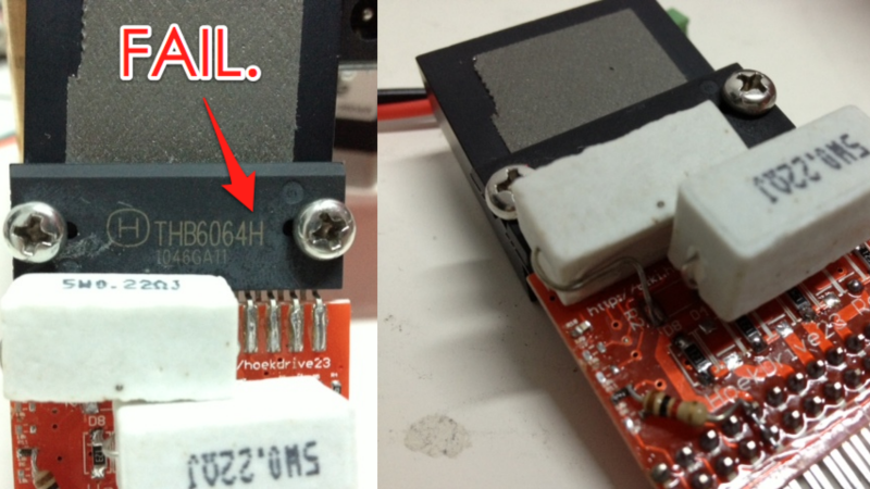
Finally, part number confusion proved to be his biggest challenge. THB6064AH is not the same as THB6064H. The difference is not a lot, but enough for him to suspect everything other than the chip itself. The good part was learning tons of stuff while probing and testing to get to the bottom of the issue.
LESSON : Please make sure your BoM lists exact part numbers used in your designs.
An example would be mixing up the ATmega328P vs the ATmega328 – the chips have different signatures, brownout, and power usage. Easy to fix, but this can cause some tense moments while trying to figure it out.
If you’re wondering where you’ve heard the name [Zach Hoeken] before, he was one of the founders of Makerbot.
Thanks [Peter Montgomery], who sent in this tip while he stumbled upon while searching for Toshiba stepper driver chips.
 Fail of the Week is a Hackaday column which celebrates failure as a learning tool. Help keep the fun rolling by writing about your own failures and sending us a link to the story — or sending in links to fail write ups you find in your Internet travels.


Sh*t happens. Hack it and carry on.
Word
A little Ubik would have fixed that up. Safe when used as directed. Do not take internally.
This is nothing compared to the Fail Bre Pettis did on Makerbot
Buh-dum-bum! Be sure to tip your waitperson on the way out!
Zach Hoeken should go back to making keyboard pants.
“…[Zach] messed up on Ohms Law.”
I think Ohm’s Law only interrelates voltage, current, and resistance; not power, which is covered by Watt’s Law.
I still have problems with SMD resistors. I know they don’t handle as much power as the through-hole versions. It’s just that my instinct that tells me “hey, this resistor is going to be dissipating a questionable amount of power” is still tuned for through-hole! 0603 handles only 100mW, preferably derated by 25% just to be sure, and that ain’t much.
If it doesn’t wreck the loop response, I’d look into replacing those big power resistors with smaller SMDs, and an op-amp to boost the current sense signal to the desired Vref. Would definitely be sleeker, and possibly cheaper.
Not bad for a first revision though. And while [Zach] was trying to track down the (wrong) problem, he:
“…learned a ton about the workings of the diode bridge, the current sense resistors, the resistors that control the oscillator, etc.”
So those two days at least count for something.
Low value sense resistors and an op-amp are good but you can go too far with this and end having PCB tracks and solder connections exhibiting more resistance than the sense resistor.
Dealing with the thermal issues of a larger resistor is much easier than dealing with the other issues if you make the sense resistor too small.
You can buy special SMD sense resistors that have four pins. Two for current and two for measurement. Since the measurement pins don’t conduct current there is no voltage drop. They are only mildly more expensive than normal ones.
With a through hole shunt you can emulate this by soldering it on the top and bottom with a hole that is not plated through (this is good for a few units, but this strange soldering would be a manual step in mass-production).
you can make a special footprint or just make sure to do the routing right
http://imgur.com/3F6jYUP
You are assuming that the whole “soldered contact” (pad) has the same voltage, determined by the current flowing through the resistor. That means you’re assuming the resistor’s contact and soldering have negligible resistance compared to the resistor.
And all that ends up depending on just how small that resistor’s value is.
Ohm’s law implies power. Voltage is work per unit charge (Joule per Coulomb), and current is unit charge per time. Going through the definitions, you can re-arrange Ohm’s law into Joule’s law. (not Watt’s law).
Then when you swap resistance for the relation V/I you turn Joule’s law into the familiar P = VI
More precisely
Pt/Q = R Q/t – which is Ohm’s law with voltage and current substituted by their definitions, and work subsituted by its definition (power x time).
smd resistors can handle a surprising amount of power provided they are soldered to a big copper area, e.g. a ground plane
There are a lot of nice, compact, stepper motor driver ICs that do current sensing using an external resistor that is expected to pass the full switched motor current, rather than using some more clever scheme, but don’t really make that clear in the datasheet. The Allegro A3967 is one example. (I suppose this should probably be obvious to someone with “experience in the field”, but it’s an easy trap to assume that these tiny SOIC motor drivers will work with similarly tiny external components, rather than needing “special care in selecting.”)
That bit about ATmegas might save my bacon yet…..
I’m just glad to see that I’m not the only one around here that forgets Ohm’s Law once in a while. :)
In place of high-wattage through-hole resistors, a coworker of mine will just stick a bunch of 0402 resistors in parallel / series. His designs work perfectly fine, is just that the guy really, really hates through-hole parts… I wouldn’t be surprised to find out that a DIP chip killed his parents or something.
Turns out its actually slightly cheaper to do it that way since manufacturing just has to buy a million 1k and 10k ohm resistors rather than thousands each of a couple dozen different values and wattages.
That made me laugh. Those killer DIPs are truly a menace!
Yes and from seeing the graphics on this site … I have a vision of an 8 pin DIP standing on legs 4 and 5, having a screen with a pic of the jolly wrenches for a head and arms 1 and 8 alternately firing projectiles in perfect cassidence.
We need a new term for hatred of DIPs pehaps for the DSM
It does not need to be a real killer, but imagine to only one time step barefeet on one – ouch. :-) We also do only SMD, the only allowed non-SMD component is the connector. But there are big 2512 shunt resistors, good for 3W or 1W at high temperature. And remember: It is not only a question of delivering dissipated power, it is always the question of getting rid of it.
Wired wound resistor for current sensing : second fail :)
These have way too much parasitic inductance. You may ending up frying the controller chip or getting very low output current.
Use resistors designed for that. usually 2012 size SMD resistors go over 3W.paralleling is also a solution.
Inductance is something that can be easily measured with a LCR meter. All the wire wound resistors I have pulled apart have been bilifar wound so the inductance would be negligible. There is no point in making assumptions – just measure your incoming stock. In any case the effect of whatever inductance that does exist will also depend on frequency.
As [Chmouss] says. Paralleling is a good solution. Then all the extra solder joints are paralleled as well and that reduces the solder joint total resistance a lot. Two single pinthrough joints will have a lot higher resistance especially compared to the sense resistor. Just remember that with SMD paralleling you *can* reduce the total size of the resistor but at the same time you increase the watts per square inch on the circuit board. You don’t have the thermal relief of the component leads that you have with a pin through so your PCB has to sink the extra heat – spread the SMD components out and use lots of copper on the PCB.
Wasn’t Zach on the design team for the Cupcake CNC and some of the later Makerbots? I would have guessed he learned a few lessons by now…
It puzzles me how so many electronics hackers think they can outsmart everyone by not doing design reviews. Are they so full of self confidence that something like checking pinout match, footprint dimensions, component pinouts, numbering orders, power requirements and all these little things is better done after you’ve layouted and fabricated a board?
With PCBs so cheap these days, I wouldn’t be surprised if some folks use them AS design review. Been guilty of this myself once in a while.
Ok. those are some pretty big beginner’s mistakes. Even before i became a student in electronic engineering i am crazy carefull with my PCB designs. Got an entire checklist of things to go through before i even think about sending the design to a PCB-fab and i go through it thrice. takes ages to work like that, but ive had no faulty PCB-designs yes so that is a plus for my wallet!
I’m no beginner lol
A couple of month ago I mad a PCB. When designing it I decided to put some pots on analog inputs so that I could adjust the incoming signal level.
The incoming signals were terminated with 75Ohm shunts and I put the post before the shunts which wouldn’t work of course – I was thinking of using 75Ohm pots to completely replace the shunts but I didn’t have any and decided to use 5kOhm pots.
In the confusion I left our some series capacitors.
I made the board and it didn’t work. I could get it partially working but spinning the pots and that made me realize that I left out the series capacitors. So I cut the traces and put capacitors in.
It’s still didn’t work. When I designed it – as a bit of an afterthought I turned it into a minimum etch board by pouring the ground plane. I didn’t have enough clearance on a trace to the crystal and parasitic capacitance dragged the crystal off frequency.
So I’ve been doing this for 35+ years and now I can make highly experience F… ups lol.
Has nothing to do with “beginner” – everyone has a bad day.