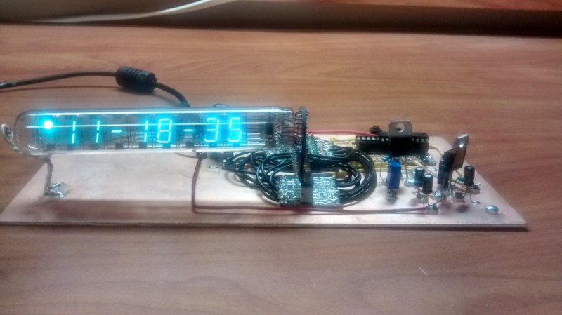
[Daniel] seems to have a lot of time on his hands for building clocks, and that’s fine by us. For his latest build, he used a vacuum fluorescent display (VFD) to display hours, minutes, and seconds using an MSP430 to drive it.
Like the analog meter clock he built recently, there is no RTC. Instead, [Daniel] used the 430’s watchdog timer to generate 1Hz interrupts from the 430’s 32KHz clock. [Daniel] wanted to try Manhattan-style board construction for this project, so he built each module on a punch-cut stripboard island and super glued them to a copper-clad board. We have to agree with [Daniel] that the bare-bones construction is a nice complement to the aesthetic of the VFD.
[Daniel] set out to avoid using a VFD display driver, but each of the segments require +50V. He ran through a couple of drawing board ideas, such as using 17 transistors to drive them all before eventually settling on the MAX6921 VFD driver. The +50V comes from an open-loop boost converter he built that steps up from 12V.
The time is set with two interrupt-triggering buttons that use the shift register example from TI as a jumping off point. All of the code is available on [Daniel]’s site. Stick around after the break for a quick demo of the clock.


A clock without ESP8266? Meh.
(;-)
Funny it’s called Manhattan-style now, we used to call it real breadboarding.
I always thought original breadboarding was more like wire wrap, but with nails in a wooden board. Or was it all point to point soldering?
Soldering became practical some time after breadboarding became a thing. Wire wrapping was the original method of connection. Fwiw, Fahnestock clips are a great way to enhance the traditional breadboarding experience if you’ve got problem connections that wire wrapping doesn’t seem to solve.
It’s from people that reinvent things and then discover that it’s an old technique so they call it something different in an attempt to make it their own.
Disagree. They call it something wrong because that’s what they read on the internet.
Way back in the day, when I started learning electronics,(1950s) breadboarding referred to a piece of wood (sometimes the piece of wood was an actual breadboard – a flat piece of wood used to knead bread on) with nails driven into it, and wiring soldered to the nails and components point to point. SInce back then frequencies used by hobbyists were almost always below 144 MHz, more typically in the 3 to 10 MHz range, we didn’t have to worry about lacking a ground plane and parasitics caused by this construction technique.