You may think you’ve built a power supply for your bench. Heck, we all do. But until you check out [Denis]’s bench power supply build, you may not even know what you’re missing.
[Denis]’s design is nearly entirely modular and targeted to the intermediate builder. It’s built on easily available parts and through-hole components. It’s got an Arduino running as the brains, so you’re going to be able to hack on the code when you feel like tweaking it. But easy doesn’t mean light on features. Let’s walk through the build together.
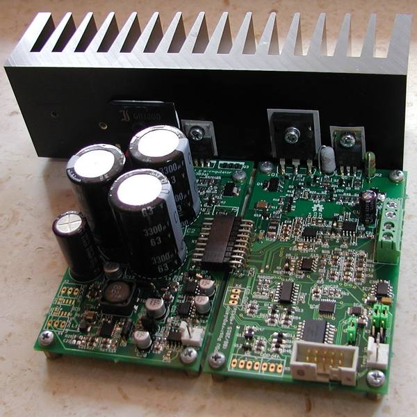
It starts off with a pre-regulator: a switching MOSFET that gets the voltage down to just a couple volts above the target value. Then it’s off to the post-regulator that includes all of the fine adjustments, the DAC and ADC interfacing to the microcontroller, and some fancy features like a “down-programmer” that turns the output off extra quickly.
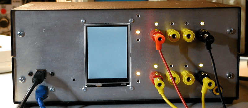
On the user end of things, [Denis] made a very sleek board that incorporates a TFT touchscreen for the controls, Arduino connections, and the obligatory banana plug outputs. There’s opto-isolation on the SPI bus, a real-time clock, and a bunch more goodies on board. He’s in his third revision of this module, and that level of refinement shows. It’s even SCPI compliant, meaning you can control remotely using an industry-standard protocol.
So what would you do with a ridiculously fancy power supply under microcontroller control? Test out battery charging algorithms? Program test routines to see how your devices will work as their batteries drain out? We have no idea, but we know we want one!


http://m.memegen.com/2hwq3v.jpg
Nice unit, but I still prefer knobs for control on a power supply.
Yes, knobs are best choice. No fancy touchscreen or keypad which are soooooo slow for setting.
Wouldn’t be hard to add, really.
Currently nothing is possible to do using TFT display (only SCPI commands over USB or Ethernet) but the main feature of the next firmware release is adding support for it. Hopefully some of you will change their mind when see how is possible to set fixed value of e.g. output voltage but also incrementing/decrementing the current value.
wow very nice build, how much can it handle surge spikes or inductive loads ???
I didn’t see anything about inductive loads — I could have totally overlooked it — but he does extensive impulse-response testing for variable loads. This was one of the best-documented projects we’ve seen in a while.
What problems do inductive loads give to DC power supplies? I thought even loop stability issues were mostly with capacitive low-esr loads.
An inductive load is XL = 2 * Pi * F * L
A capacitive load is XC = 1 / (2 * Pi * F * C)
So they are not that different in math.
Capacitors cause feedback loop delays which can cause overshoot and oscillation in poor designs.
Inductors cause a back EMP to reflect back into the PSU and this can cause overshoot and oscillations in poor designs.
Back EMF’s from inductors can also cause an over voltage condition in the PSU resulting in components operating or failing to operate at a voltage above their specified voltage.
Thanks for question. I added some inductive and capacitive load results under Measurements section.
How about adding programmable ripple (freq/amplitude) and noise simulation to test robustness of down stream regulation.
I’m confused, how is the preregulator any improvement on a linear regulator?
It’s pulsing charge into a capacitor with no inductor.
I don’t get it.
more efficient I think. It’s job is just to provide a few volts more than the post regulator needs for the set voltage.
The limitation of a linear regulator is the heat that the regulating component can dissipate. Just say we have a 50 Watt Reg with a Max of 50V …
@0V we can have 1 Amp because the other 50V @ 1 Amp comes to 50W
@5V we can have 1.11 Amp
@10V – 1.25 Amp
@20V – 1.66 Amp
@25V – 2 Amp
@30V – 2.5 Amp
@40V – 5 Amp
@45V – 10 Amp
@47.5V – 20 Amp
This is backwards to what we normally want in a PSU. We more often want higher current at lower voltages.
To fix this problem you can use a pre regulation stage that is not linear ie a switching regulator to bring the voltage down to a little more than the normal reg needs and this reduces the power the normal reg has to dissipate. You can also use primary side regulation with a transformer to achieve a similar thing but primary side regulation has a limited range with inductive transformers.
I think I get it now. It looks like an overvoltage shutdown circuit, because that’s exactly what it is. It’s driven from the raw rectified waveform and resets every half cycle. So it’s switched on as the voltage rises, the bridge conducts when that exceeds the voltage on the main capacitor and then a predetermined voltage above that the cycle is shut off and the circuit has to cope until the next half cycle.
Seems like an odd design choice but it is more efficient than a linear regulator.
It is a standard ‘chopper’ regulator, similar to those used in a light dimmer. The inductor is not necessary since the input voltage (the unfiltered transformer output, strait out of the rectifier) is already varying. You turn the switch on at the zero crossing, and then turn it off when the load capacitor is charged to your desired voltage. They are fairly common as pre-regulators since you do not need good regulation on the pre-regulator and they save you an extra inductor/capacitor
Amazing project! Really high level of work in my opinion, very inspiring. Well done!
Nice project.
Any videos?
Nice project. Well thought out and executed. Great job. Thanks for the interesting and informative writeup Elliot.
Gawd, what an ugly physical build. Why put so much effort on the electrical design and internals then toss it all in the end product presentation?
because it’s still in design and prototype stage
Yes it’s in prototyping phase, a little bit nicer front panel is visible here http://www.envox.hr/eez/images/arduino_shield_mounted.jpg but still without acrylic mask.
What is the input voltage for this power supply?
There is multiple possibility and of course depends of what you wants on your output. I’m using currently two dual channel model: 0-40V/5A and 0-50/3A. First with 40 VAC (57 VDC max rectified) and second with 48VAC (70 VDC) main transformer. Small auxiliary transformer has 12VAC on its secondary.
Where did you get the banana jacks?
TME.eu … all details are available in BOM on GitHub repository
BROKEN LINKS. PLEASE FIX.
please fix the links.
Which one of many :) ?
Please visit https://github.com/eez-open/psu-hw if above mentioned links to our server is not responsive.
Project just launched on crowd supply:
https://www.crowdsupply.com/envox/eez-h24005
Nice Denis. Ordering one now!
Thanks Alan!
I bought one as well. I rarely do an impulse purchase but I’ve needed a home PSU for a long time, and this one looks awesome. I can’t wait to read through the technical description on your home page describing all the parts and the test equipment you used.
Thanks Erik, we are almost there, just few backers are missing to make it happen.