Spice is a circuit simulator that you should have in your toolbox. While a simulator can’t tell you everything, it will often give you valuable insight into the way your circuit behaves, before you’ve even built it. In the first installment of this three-part series, I looked at LTSpice and did a quick video walkthrough of a DC circuit. In the second, I examined two other parts of Spice: parameter sweeps and AC circuits. In this final installment, I want to talk a bit more about real-world component performance and also look at modeling transformers.
Recap
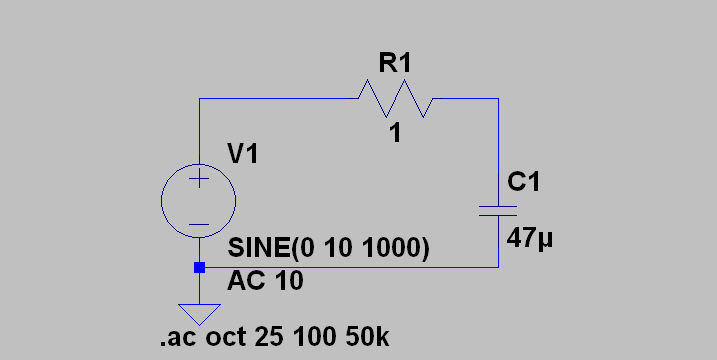 Last time we looked at a low pass filter, but it wasn’t practical because the components were too perfect. Only in simulation do voltage sources and wires have zero resistance. There was no load resistance either, which is unlikely. Even an oscilloscope probe will load the circuit a little.
The resulting AC analysis showed a nice filter response that was flat to about 1 kHz and then started roll off as the frequency increased. Suppose the source had an 8 ohm series resistor. How does that change the circuit response?
A Real World Circuit (Almost)
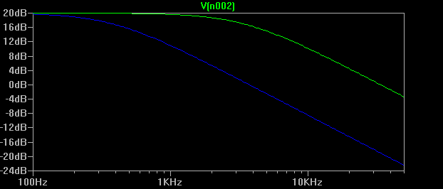 That’s an easy question to answer with Spice and the plot on the left makes it easy to see. The green trace is the original response, and the blue trace is the new curve. You can see the roll off starts earlier, and attenuates faster. This is probably more accurate but still isn’t entirely correct because there is no load connected across
 C1.
That’s easy to fix, though. Suppose this were feeding an amplifier and the input resistance is 2K ohms. The resulting plot isn’t much different. However, if the load gets close to the value of R1, it makes a big difference. Look at this plot (I used the annotation feature to add some labels and arrows):
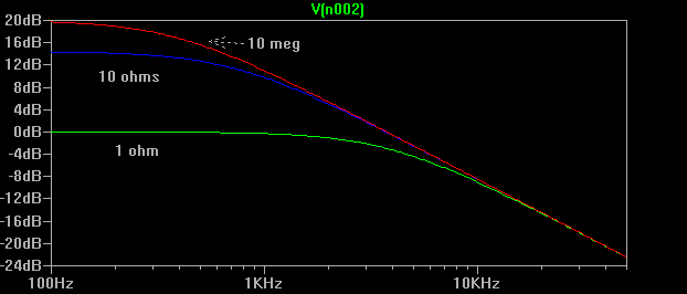 When the load is 1 ohm, the loss is greater than in the other cases, although the pass band is much flatter.
Of course, there are still some inaccuracies. Wire, for example, has resistance, but unless you have very long wires, that probably doesn’t matter. A normal resistor doesn’t have much inductance unless it is wire wound either. Capacitors have parasitic elements that differ based on the kind of capacitor. Spice can simulate all of this if you ask it. Try right clicking on the capacitor and select an actual vendor’s part. That will fill in things like the equivalent series resistance and other parameters of the capacitor. You’ll see the curves change slightly based on the unit you select.
Another consideration in real world circuits is limits. A resistor in Spice can dissipate an infinite amount of power. In real life, resistors and other components eventually burn out or fail when overstressed. Keep that in mind when testing designs with any simulator.
Transformers
One item that can be tricky to model in Spice is a transformer. You won’t find a transformer in the components section of LTSpice. Instead, you’ll have to build one out of inductors. After all, a transformer is just two inductors (the primary and the secondary). Due to coupling, changes in the magnetic field of the primary induces a current in the secondary. Exactly how strongly coupled the two coils are will affect the transformer.
In a properly designed transformer, the key design feature is the ratio of the number of turns of the coils. A transformer with 1:10 turns will step up voltage ten times (or, flip it around, and it will reduce voltage by a factor of 10).
To model a transformer in Spice, you create an inductor for the primary and the secondary. The inductance values aren’t very important, but the ratio of values is. The rule is that the inductance ratio will be the square of the turns ratio. That is, a 1 Henry primary and a 100 henry secondary will represent a transformer with a turns ratio of 1:10.
What makes the coils a transformer is a K-statement. Once the inductors are in place, use the Spice Directive icon (the icon with .op on it) to insert a statement like this:
K1 L1 L2 1
Note there is no period in the front of K1. This defines a transformer consisting of L1 and L2 with a coupling coefficient of 1 which is sufficient for most of what you will want to do. If you need more transformers, you will use K2, K3, and so on. Transformers with multiple windings are possible. Just list them all in the same K statement.
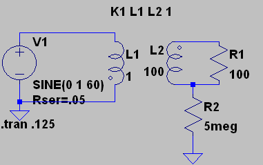 There are a few things to note about the schematic to the right. First, with Spice you can’t directly connect a perfect voltage source to an inductor. That’s why
 V1 has a small bit of series resistance included. Secondly, you can’t have any totally isolated circuitry in a Spice schematic. I didn’t want a common ground, so I added R2, which, at 5 Mohm, might as well be an open circuit.
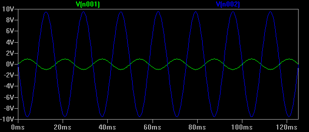
Because the inductors have a 100:1 inductance ratio, the transformer has a 10:1 voltage ratio. Logically, then, a 1 V output from V1 should wind up as 10 V across R1. The simulation output clearly shows this is the case (see below).
You probably know that transformers “reflect” their secondary impedance at the square of the turns ratio. Looking into the primary of this transformer, you should see a load equivalent to 1/100th of the secondary’s load. In other words, the current out of V1 should be the same as a 1 ohm resistor.
Since V1 is set to 1 V, it doesn’t take a calculator to know that 1 V into 1 ohm should result in 1 A. If you click the probe inside V1 to measure current, you will see a sine wave going from -1 A to 1 A, just as you’d expect.
Spicy Development
Spice, LTSpice, and similar tools are an excellent way to experiment and gain insight into electronic designs. The examples here have been simple, but you can easily grab some more complex ones at the Linear website or the Yahoo group.
You do have to remember, though, that simulation can only get you so far. Eventually, you have to heat up a soldering iron and build these designs to see how they will behave in the real–and less than ideal–world.


The spice must flow.
I use Spice on a daily basis and if you want to have something usable you should at least set a typical ESR for your Capacitors and Inductors. The ideal value will lead you nowhere, same for transformer the coupling factor from 1 to 0 is rarely 1.
Here is a good link by the LTSpice author himself: http://www.linear.com/docs/40277
What do you mean by “author himself”?
https://en.wikipedia.org/wiki/SPICE
the LTSpice author
IMO, the LTSpice Yahoo group is a must. The questions answered and the resources available there are really helpful.
Yes, the LTSpice Yahoo Group is a great resource. Don’t forget the Files area too.
One thing the Author of this HaD article has seemingly ignored is the unofficial LTSpice Wiki:
http://ltwiki.org/index.php5?title=Main_Page
FYI: http://www.coilcraft.com/search.cfm/b/q?k=LTSPICE&x=0&y=0
They make inductors/transformers etc. fFllow the link to their search pages and you’ll find
– Model libraries for Linear Technology SwitcherCAD III
– Implementing models in LT Spice
– Coilcraft SPICE Models, PSPICE Models and S-Parameter Files
– Coilcraft power supply simulation tools – links for the various chip vendor simulation tools
– TDK/EPCOS: http://en.tdk.eu/tdk-en/523002/design-support/design-tools/inductors/model-libraries-for-smt-and-leaded-inductors/ltspice
– Sumida: http://products.sumida.com/ProductsInfo/ProductGuide/PowerInductors/ See “INDUCTOR MODELS FOR LTSPICE” link there
– Würth Elektronik http://www.we-online.com/web/en/electronic_components/toolbox_pbs/LTspice_III_IV.php
– Vishay: http://www.vishay.com/how/design-support-tools/ spice models, 3D models
Those are google results for “ltspice inductor model”.
I use LTSpice regularly, albeit for usually for simple stuff. I took the plunge when CircuitLab became nagware and haven’t looked back since.
But I recently came across this website:
http://www.precisionmicrodrives.com/application-notes-technical-guides/application-bulletins/ab-025-using-spice-to-model-dc-motors
I won’t pretend to understand it fully, but they are simulating even the mechanical aspects of a motor system (inertia, friction, gravity etc.) in Spice, using inductors, resistances and voltage dependent sources.
When you boil down to it mechanical systems and electrical circuits can be expressed as a system of differential equations. Things like that can be (have been) simulated by analog circuits/computer well before digital computers. Pretty cool stuff actually, but my brains would melt working the math these days.
I do a lot of oddball power supply doodling, so having the convenience of a large quantity of power supply support parts – caps, inductors, diodes, transistors, MOSFET was handy. There is good correlation between the stuff I simulated and built. They pretty much work without too much tweaking around which I like.
TI has licensed a commercial simulation package TINA for use with their parts. Funny thing is that I tend to use more TI parts than LT parts, but I still ended up using LTSpice even if I have to use their chip model as stand in for other vendor’s chips.
LT uses encrypted models, so chances are that they can use more detailed internal model and not worry about trade secrets. I like their package as it does not require registration, nor using their parts and the installed directories can be copied and run as is.
I’ll take a look at circuitlab.
6000 watts is a lot to put through that transistor
what pin is the current sense pin?
sorry i posted to the wrong place that is why i reported so you mods can remove them