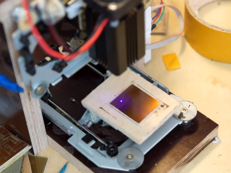
[Neumi] has built a CNC Laser using CD-ROM drives as the X and Y motion platforms. The small 405nm laser can engrave light materials like wood and foam. The coolest use demonstrated in the video is exposing pre-coated photo-resist PCBs.
With $61 US Dollars (55 Euro) for the Arduino, stepper drivers, and a laser in the project, [Nuemi] got a pretty capable machine after adding a few parts from the junk bin. He wanted to avoid using existing software in order to learn the concepts behind a laser engraver. In the end, he has a working software package which can send raster scans to an Arduino mega. The mega then controls the sync between the stepper and laser firings. The code is available on GitHub.
The machine can do a 30x30mm PCB in 10 minutes. It’s not about to set a record, but it’s cool and not at all bad for the price. You can see the failed PCBs lined up in the video from the initial tuning, but the final one produced a board very equivalent to the toner transfer method. Video after the break.


I’m considering building a laser PCB photo etching system.
He states that he gets about 100 dots/cm, which is about 250 dpi resolution. That would make fairly high-resolution PCBs, but I would like to see confirmation from him that he can expose individual pixels, or lines 1 pixel wide reliably.
I’m wondering if his 100 dots/cm is positional resolution, and not the spot size of the laser.
Also of note, there is little info about this project other than the video. The GitHub repo has a hand-drawn schematic (nothing wrong with being hand-drawn, that part’s fine) and 500 lines of sketch/processing code. No construction images, no written description, no idea what laser to buy.
This is a fine project, I think it’s neat and clever and useful, but it’s ‘kinda hard to reproduce from just a video and the YouTube notes, hey?
(Project’s fine, but I’m thinking that the description is a little thin for a Hackaday post.)
A better way to go about this would be “isolation etching”, not this. Sort of how you’d use a CNC mill with an engraving bit, you want to trace the contour of your tracks, not scan the entire raster; then the resolution doesn’t really matter, only how tightly you can focus your spot – which should be equal to your desired isolation.width to avoid multiple passes and the return of the resolution issue.
The formula for minimum spot size is proportional to focal length. His setup has the laser a long way away from the platen, so I assume his spot size is rather large.
He could get a much smaller spot by focusing closer. Turn the vertical axis sideways so that the transoms are parallel to each other (but 90 degrees off), so the laser can be close to the platen.
Also, I agree that isolation etching via general X-Y positioning is the way to go.
It’s also inversely proportional to wavelength, and in this case, 405 nm is pretty short. Also, if he decreases the focal length, the spot intensity goes way up, which would mean that he can scan much faster for the same power.
Er, proportional to wavelength. I was thinking about Rayliegh range instead of spot size. ;)
Coherent laser light does not behave like regular light about focusing. Anyway, those blue laser are known to have a quite bad dot,elliptical and very asymmetric.
Not only the above concerns, but anytime you try to focus things smaller, you have problems with the light spreading apart anyway, a property known in optical circles as the diffraction limit. There is a finite limit to the smallest spot size a lens of given aperture(diameter) can create. Generally, the smaller the lens and source beam, the larger the smallest spot size. This effect is also very dependent on the wavelength of the light being focused, which is why Blue lasers are used now for optical storage: the wavelength is a lot shorter than infrared or even visible red, therefore allowing a tighter spot. Most of the lenses available from Ebay or other sources are not up to snuff to even approach the theoretical minimum spot, so it is not surprising he would have difficulty getting it down much smaller.
This is one of the many reasons most high quality laser cutters use a beam expander for the entire optical path up until the final focus stage, because it gives you a better final spot size(less diffraction) and therefore better beam quality and better resolution.
Also, lengthening the distance required to focus the beam results in a shallower angle and better depth of field. This gives you a better cut.
There is a lot involved in building an optical system, especially with Lasers, and a lot of this stuff, unless you are familiar with optics, will be easily overlooked!
Spot is pretty bad in these. It needs a spatial filter – two identical lenses and a mask with a circular hole. The first lens performs a Fourier Transform on the input beam shape. The hole stops or filters out the non-circular and asymmetric and off-axis components which are spread out “spatially”. The second lens performs the inverse transform and gives you a clean Gaussian beam. Common practice in lab work using a pair of microscope objectives. I think the very nice little lenses from scanners might be side-cycled for this. If they were quartz they would would be great provided focal length is short enough. Worth some experimenting. Search Spatial Filtering for the equations.
Alternate is a length of single mode fiber which will have a clean Gaussian output no matter what you stuff in the other end. Hmm. And the LASER can be on the table and the head that moves just holds the end of the fiber and a little lens. Graded index cylinder lenses are small and pretty low cost – even in quartz. Now, where to get single mode fiber in discarded gear?
My first thought was the same but there are advantages particularly with analogue circuits if you do it his way. It is a real drag trying to write Gcode to remove areas of copper with a vector machine. The disadvantage is time.
I considered doing something like this but I abandoned the project because of safety issues.
He is using a 12 Watt LASER. He is obviously wearing expensive LASER filtering goggles and that doesn’t cut it for safety. The whole thing should be in a light proof box and have something like a webcam so you can see what’s happening inside.
So yeah – excellent idea but research what the full costs will be first.
He says that it is a 150 mW unit. Where did you get the 12W figure from?
Well now that I think about my estimate is wrong. I saw the PSU @ 12 Volts and 1 Amp (12 watts) but that can’t be right unless he is using a dc-dc converter.
Thanks for pointing that out.
That’s very impressive for 150mW. Especially the foam melting.
Maybe I need to revisit this.
It’s me, Neumi.
Yeah it actually was an 150mW 405nm laserdiode. The 12W where the consumption of all electronics including motors and laser.
12W? You sure, as this looks a lot like 500mW laser from:
http://www.o-like.com/index.php?main_page=product_info&cPath=8&products_id=92
Actually, his youtube video says it’s 120mW. Anyhow, use goggles. Good ones.
At 12W output it could probably burn the copper off without any additional help, the photoresist would be brutally overexposed no matter how fast you’d move the table…
At 12 watts or so you can paint the board and burn the pain off where you don’t need PCB traces. Slooooowwwwwwllllyyy
No, that would not be slowly :-) Burning white paper with ~50mW of 405nm is slow (<1mm/s) but burning a thin layer of paint with 12W will be blazingly ( :-) ) fast.
Ok, The LASER that I bought to do this before I realized the safety implications was like 800nm or something like that (not visible light) and 18 Watts.
Is Mega really necessary, or could I use a Uno?
Would a laser salvaged from a dvd burner be adequate for this project?
A laser salvaged from a DVD burner will work, but not in his configuration. The DVD laser wants to be about 3mm from the surface for etching.
There’s some published papers on doing this, such as this one:
http://diyhpl.us/~bryan/papers2/optics/photolithography/High%20resolution,%20low%20cost%20laser%20lithography%20using%20a%20Blu-ray%20optical%20head%20assembly.pdf
That paper notes a 50uM spot size from using a DVD laser – more than enough resolution for a PCB.
Also note that his setup can only expose PCBs of about an inch square – you might want to buid a system with a larger expose area, such as using two scanner transoms instead of two DVD transoms.
you can’t expose pcbs with DVD lasers. if you want to salvage a laser then from a blu ray player
May I know why? Is the photoresist unsensitive to the red radiation in a dvd burner diode?
An Uno would work too :)
I’ve always wanted to buy one of these things:
http://www.dx.com/p/neje-jz-6-red-laser-engraving-machine-laser-printer-transparent-422084
Just for fun. I’ve got access to a 60W CO2 Laser engraver/cutter, but this thing looks fun.
And the idea of making PCBs with it is interesting…
I have a few of those and they are truly crap. The software you drive them with is so mind bogglingly pathetic that you have to wonder why they even bother producing it.
They are trivial to make a lot better. swap out the controller board and you can use a lot of good software. China laser cutters/ engravers are awesome if you can tinker. and even after the tinkering they are still dramatically cheaper than one already done.
This is true. Both my laser cutter and CNC PCB thing use Marlin and they are as perfect as anyone could wish.
What laser cutter do you use?
Thanks for that link..!! $60-80 for a complete kit is about as much as i’d pay for a ~500mw laser alone. Work space is 30mm = 1.18 inches, I know that’s all the travel I get from a CD-rom sled but that sounds lovely.
I have always wanted to do this, I have about (4) CD-rom carriages , (4) 3.5″ floppy disk drives , and 2 scanner beds with stepper motors. And a few old PC PSU. So I could make a few Laser “cutters/engravers”, 3-D printers, Pen plotters, or Dremel CNC machines if I knew what software and control boards to use. And decided on a rock solid small frame. Youtube has a few videos under “diy cd-rom cnc” .
My birthday is coming up and this is what I want, a small, cheap DX laser cutter/engraver . I might need a GRBL board to upgrade it. Unless someone can suggest a better Maker Community Open source 2 or 3 Axis Control board and Software thats cheap ?? Might need some proper wrap around Goggles and a Big Cardboard Box too.
2 axis, 500mw laser engraver to get my feet wet. Then I want to make a 2 axis, 2 watt laser cutter from my 10″ printer beds, then Make some bigger 3 axis CNC machine that I can swap heads out for Pen plotters, Laser Diodes, 3D printer hot ends, Dremel tools..
CHEAP is the name of the game..
One step further:
https://www.mikrocontroller.net/topic/391759#new
All drilling of holes should be done prior to etching to prevent tearing of traces.
That is how the professionals do it.
Use good drill bits,they do that to be able to do the metalization process for the vias.
It said nothing about the laser, most of us do not have something like that in our parts bin and 150mW lasers are rather bright. also does he or is he using protective eye wear that thing can do some damage
Hey :)
I used a 150mW 405nm laser diode with TTL driver. These are about 35€ on ebay from China. I do wear bandpass filter laser googles exactly for that wavelength. 405nm @ 150mW is no piece of cake … especially the reflections from the copper surface is nasty.
Where can I buy an laser with he uses for PCB?
like almost anything on ebay ;)
http://www.ebay.de/itm/405nm-150mW-Violet-Purple-Blue-Laser-Diode-Dot-Module-12VDC-w-TTL-Good-Cooling-/130955431574?hash=item1e7d8d4e96:g:KsAAAOSwGvhUKxSL
please buy bandpassfilter goggles too!
http://www.ebay.de/itm/Laserschutzbrille-200-NM-540-NM-mit-Etui-/261118699618?hash=item3ccbe32862:m:mHhZNTLD44Fl8OTi_hxgvwA
Just wondering when CD-ROMs had blue laser diodes?
IIRC BlueRay/HD-DVD drives have them…
They’re good for about 250mW. You can push then to 400mW but they wont last long.
Oh I am aware Bluray have them but CD-ROM?
You know, I always wondered if you could take a LightScribe drive, and make copper clad + photoresist boards that would fit in it, and then directly expose the board with the laser printing mechanism.
that won’t work. wrong wavelength
PCDB ?
Would be interesting if CD shaped per-sensitized PCBs were made
I still prefer the way Diyouware.com solved the problem. Why not just use the complete diode/lens pickup assembly from your BluRay writer? With that, setting the focus can actually be done ‘automatically’, as you already have a sensor inside the assembly to read back the reflected light and adjust the lens position.
What copper PCB do you need? Does it need to be photo-sensitive? positive or negative?
Can’t a high power laser burn and remove the copper exactly like a CNC from a raw copper PCB?