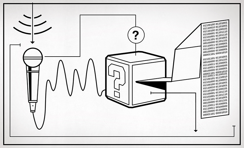
In the first article about measurement systems we looked at sensors as a way to bring data into a measurement system. I explained that a sensor measures physical quantities which are turned into a voltage with a variable conversion element such as a resistor bridge. There will always be noise in any system, and an operational amplifier (op-amp) can be used to remove some of that noise. The example we considered used an op-amp in a differential configuration that removes any disturbance signal that is common to both inputs of the op-amp.
But that single application of an op-amp is just skimming the surface of the process of bringing a real-world measurement of a physical quantity into a digital system. Often, you’ll need to do more work on the signal before it’s ready for sampling with a digital-to-analog converter. Signal conditioning with amplifiers is a deep and rich topic, so let me make it clear that that this article will not cover every aspect of designing and implementing a measurement system. Instead, I’m aiming to get you started without getting too technical and math-y. Let’s just relax and ponder amplifiers without getting lost in detail. Doesn’t that sound nice?
Operational Amplifiers
Taking a step back, let’s look at some basic op-amp configurations. The fundamental op-amp circuits are designed to perform mathematical operations. (I don’t need to draw any more attention to what just happened, do I?) This means we can use an op-amp to add, subtract, multiply, or divide and this might seem like a simplification of an op-amp but there are some complex calculations that can be done with these basic operations.
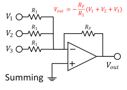
Using an op-amp, we can take several voltages and add them together to get a summation of multiple inputs. We can then take that sum and divide it by the number of inputs we added together to get an average value of all the inputs. And all within the same op-amp circuit, we can amplify the signal with a desired gain by choosing feedback resistor values appropriately.
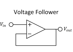
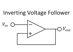
Another use for an op-amp is a voltage follower. In the voltage follower configuration we have a gain of 1 (unity gain) so we get out the same voltage that we put in. This may seem like a waste of an op-amp but it’s crucial when we want to isolate one part of a circuit from another. A typical use case would be in between the resistive conditioning parts of a circuit and the bit that measures the conditioned signal. The high impedance of a voltage follower (or buffer) is what reduces the loading of a circuit that is being measured. A voltage follower can be thought of as a multiply by 1 operation, which coincidentally is a beautiful segue into an inverter configuration. An inverting buffer is a voltage follower that has reversed polarity, or you might think of it as a multiply by -1.
Instrumentation Amplifiers
By this point we have all either used an op-amp or are at least understand how they are used. The LM386 audio amplifier in an Altoids tin or cigar box is a rite of passage where I come from. However, the instrumentation amplifier (in-amp) tends to be thing of mystery. Let’s get over that barrier to entry and learn what an in-amp is and how to use it, because when you’re interested in precision measurement, in-amps are where it’s at.
We saw that the op-amp is a device that allows us to do mathematical operations on voltages, in-amps take the basic operations and build on them. If you read a datasheet or application note you might come across what is referred to as a three op-amp in-amp design. Which is exactly what it sounds like: an in-amp made up of three op-amps. This might look intimidating but if we take it one piece at a time it’s nothing we haven’t seen before; the basic idea is to use two op-amps to buffer the input signals and a third to cancel out the common-mode noise.
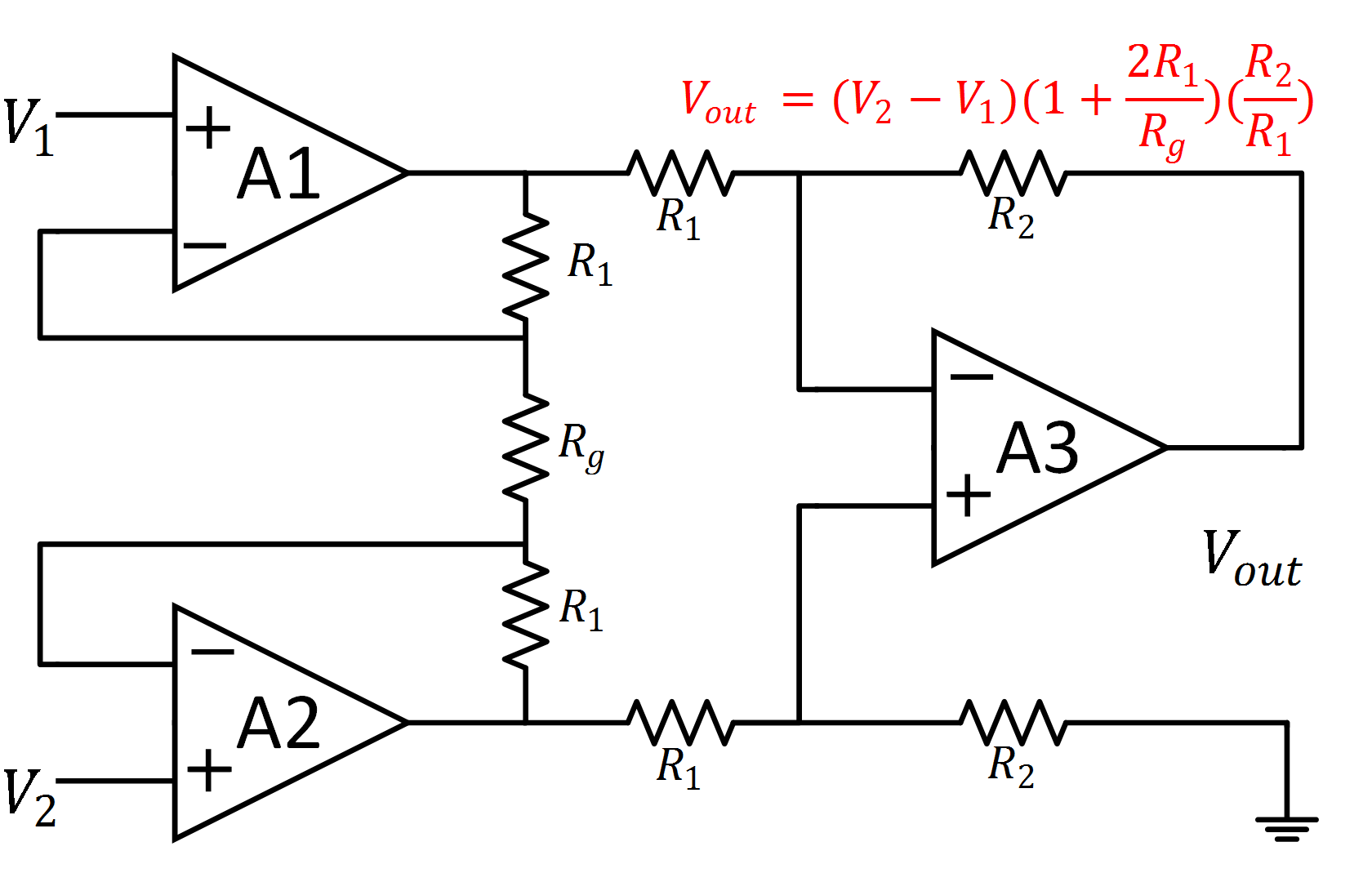
Amps A1 and A2 are configured as non-inverting with gain. The amp A3 is configured as a difference amplifier using amp A1 as the inverting input and A2 as the non-inverting input. As you can see from the diagram, you can tweak the gain on the input stages as needed. I’ll leave you alone with the red equation included in the image if you just need to get your math on.
So that’s it? The mysterious instrumentation amplifier is just three op-amps? Yes and no. When you build one yourself, it is. But when you buy a dedicated in-amp IC, you’re getting these op-amps with the gain resistors pre-set and matched. Moreover, the op-amps themselves are made on exactly the same process — indeed on the same piece of silicon. Because everything is on the same chip, temperature differences between different parts are also likely to be minute. In short, you’re getting the same circuit made to tolerances that would be expensive, or fiddly, to replicate with individual parts.
Of course, if you want to experiment around with instrumentation amps and see how they can improve your signal path, there’s no substitute for building your own. But when you have settled on a design, you’ll probably want to grab one off the shelf. Either way, the in-amp can help your tiny and weak sensor voltage blossom into something suitable for the next stage in our signal-conditioning saga: analog to digital conversion. And that’s where we will pick up next time. Stay tuned.


Just working through my first project with an Instrument Amplifier for a weighing scale so nice to see a write up about it. I’ll say nothing about the fact it took me two days to realise -Vin was not GND and that my salvaged load cell was not by extension ‘total crap’.
$1 million to anyone on here that knows about and has used op-amps and has never made that mistake.
Safe as money in the bank is that bet. :)
Yes in genuine OpAmp Dollars :P
Open-loop dollars. Expect some error in the change you get back.
Haha, back in the days of crappy internets it took me weeks to realize.
Where I live, its practically impossible to get in-amps. I work in a lab and I use a LM324N with external resistors to the same end: The first two amps are buffers, the third amp is a difference amp with gain =1 and the final amp, the fourth, is the gain amp.
If we need to offset the output, then the 4th amp is used as a difference amp between the output of the third amp and a variable voltage source and the output of the 4th amp goes to an external LM741 to be the gain amp. This circuit served us really well to measure temp with an RTD+arduino and with a bit of more careful assembly will allow us to measure strain gauges (which right now is a WIP).
I’m sure you can buy instrumentation amp chips from China through aliexpress and get it delivered to any hellhole!
Not when:
– There is currency control, and the government doesnt sell you any foreign currency
– You cant use your own personal earnings to buy anything from abroad unless you have an overseas bank account (and make the transaction using that account)
– If you want foreign currency, you have to go to the black market at >50x the “official” rate
– The lab is government funded and has budget only to pay salaries and utilites (power/water/etc). Nothing else
– If you want to pay it from your own pocket, bear in mind that your salary will be around 40USD a month and you still have to eat and sleep, preferably under a roof, which goes for half of that for a single room.
So, in short, nope, in this hellhole you cant unless you’re in bed with the government and/or do all kinds of shady and/or illegal deals OR you have family overseas able and willing to lend you a hand :p
That reads like your playing Civilization IV on Deity on Archipelago map.
Well, havent played any RTS since WH40K+ but Ill take that as “something really hard” :p
Its interesting to work like that with sticks and stones though. For instance, about a year ago we managed to restore an OLD servohydraulic test bench that worked with pure analog circuitry and it was a piece of equipment no longer available in the manufacturer catalog (its THAT old, you controlled it by wiring a board/panel and using an analog signal generator!). It measured position, velocity and torque, we contacted the manufacturer and the closest spares were 4K USD (just for the sensor pack!). We got it back to work with an Arduino Uno, a 1024 ppr rotary encoder, a 1/8 frequency divider, a frequency-to-voltage converter and we even managed to install a separate pump for the oil heat exchanger to keep the working fluid below 40C (measured with a LM35). We still need to make the torque sensor, but going from >4K to about 100 USD… its something :)
Soon I’ll be working on measuring deformation (<1mm) with a strain gauge. We'll feed it with a constant current source, and as you'd expect, the signal is going to be very weak and we'll be using the circuit I described in my post (but with an added LP filter at the output stage). Wish me luck! :D
Do you live in North Korea?! Just kidding
Let’s just say that if it werent for the harsh political climate, Cuba would seem a very interesting alternative…
We didnt. It was thanks to the students that did the restoration/upgrade (it was their undergrad thesis). To be honest, I dont know if they had access to foreign currency or they resorted to “alternate currency transactions”, in any case, they bought the Arduino+encoder from their own pockets and someone they knew who went abroad brought them… back then (2 years ago) it wasn’t that expensive. These days you still can get some “mainstream” stuff but at ludicrous prices (for instance, I was told recently that a Full Professor’s hourly base salary is not enough to buy a pushbutton and he/she would have to work a whole week just to buy an LM35… do the math).
Does Bitcoin help with the currency issues at all?
LM741? you live in the eighties?
I wish I lived in the eighties! I live in a hellhole! xD
Now, seriously, thats the kind of stuff you can get easily over here.You gotta work with what you have available (and can afford) :p
uA741 1968
Argentina?
The inverting voltage follower image shows positive feedback. That is clearly a very bad thing to do.
Came here to say the same thing. You’ve built a comparator with as much hysteresis as you can add.
Same thought when I saw this image.
This thing will swing from rail to rail like crazy
This configuration inverts the usefulness of its inputs
Sorry – This article contains errors!
The seminal work on Opamps from TI:
http://web.mit.edu/6.101/www/reference/op_amps_everyone.pdf
(This is an older edition, and it is also available as hardcopy.)
I’ll second “op-amps for everyone” being really awesome! “The Art of Electronics” also has a good section on instrumentation, but it ain’t free.
The National op-amp application book/guide is great if you can find it. And “Quadzilla” was a booklet full of applications using the LM324 I think. I spent many an hour grazing in those fields.
Here’s a simple design for some differential scope probes. http://levysounddesign.blogspot.com.au/2016/02/differential-scope-probes.html
My goodness… at the first figure the “inverting follower” is as bad as it gets. After this blatant error, I decided it is not worth it to continue reading.
I thought the same thing, the “Inverting Voltage Follower” is wrong.
The positive feedback will saturate the output.
It’s possible to make an inverting buffer using one buffer followed by one inverting amplifier with gain of “-1”. To minimize the troubles related with the tolerance of the resistor it’s possible to use an precision differential amplifier as the INA105 and others.
I wrote some articles about OpAmps. The articles is in portuguese but there is one tool in the site to translate the articles.
I imagine that one of the main reasons why op-amps are not used as much as they could be by hobbyists is because many electronic texts focus on the traditional dual-supply topologies. In many projects having to generate +12V and -12V supplies to use an op-amp is simply not worth it. Single supply topologies are much more practical and seem to be used in many designs/places but there’s very little information on them. Perhaps hackaday could shed some light on single-supply op-amp designs/topologies.
here are some resources on single supply design:
– http://ocw.mit.edu/courses/media-arts-and-sciences/mas-836-sensor-technologies-for-interactive-environments-spring-2011/readings/MITMAS_836S11_read02_bias.pdf
– http://web.mit.edu/6.101/www/reference/op_amps_everyone.pdf
– http://www.ti.com/lit/an/sloa030a/sloa030a.pdf
Good links. Unfortunately, the 741 and 324/358 Op Amps are not well suited to single supply operation, so it would be nice if there were some jellybean Op Amp that we could all agree to use in place of them.
Almost any “rail-to-rail” opamp will work well@single supply as long as you’re not on a tight budget.
to name but a few: MAX4475/77 (max +6Vcc), TSX9292 (max +16Vcc), TLV2172 (max +36Vcc)
these above are low noise and relatively fast (10Mhz GBW) hence suitable for audio up to ultrasound. Depending on the application, you might need others optimized for one or another thing.
I can’t believe that no one has fixed the “inverting amp” schematic yet.
HI, just Look litle better he make not one but 2x errors :)
Hint, wrong feedback in both cases…
The guy who wrote the article has obviously no clue what he’s doing (e.g. the “inverting follower”).