If you want a stable oscillator, you usually think of using a crystal. The piezoelectric qualities of quartz means that it can be cut in a particular way that it will oscillate at a very precise frequency. If you present a constant load and keep the temperature stable, a crystal oscillator will maintain its frequency better than most other options.
There are downsides to crystals, though. As you might expect, because crystals are so stable it’s hard to change the frequency much when you want a different one. You can use a trimming capacitor to pull the frequency a little, but to really change frequency, you have to change crystals.
There are other kinds of oscillators that are more frequency agile. However, they aren’t usually as stable. To combine flexibility with crystal-like stability, you can use a Phase Locked Loop (PLL). Many modern systems use direct digital synthesis, but the PLL is a venerable and time-tested technique.
Basics
The basic idea is simple. A PLL uses a crystal oscillator, but it isn’t the main output. The primary output is from an adjustable oscillator, usually a voltage-controlled oscillator (VCO). Consider a simple (but impractical) example. Suppose the VCO should put out the same frequency as the crystal oscillator. The loop part of PLL is where you compare the two frequency outputs and develop a voltage proportional to the difference. This voltage adjusts the VCO until the output matches.
This raises two questions: First, why not just use the output of the crystal oscillator? Second, how do you compare the output of the oscillators?
Phase Comparators
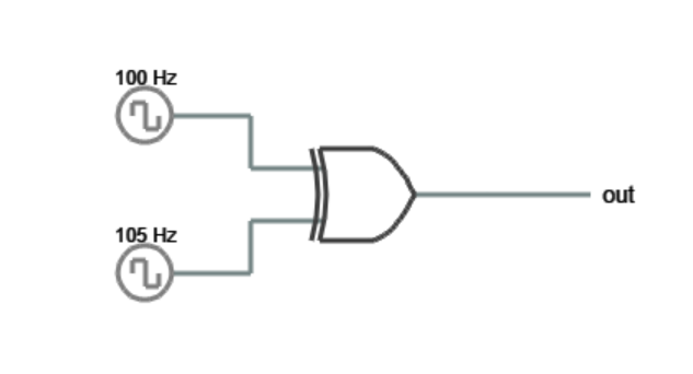 Let’s answer the second question first. Consider the case where both oscillators output square waves. You could consider the low level a logic zero and the high level a logic one. Feeding both outputs into an XOR case will result in an interesting output.
If the two signals are exactly in phase, then the inputs will be either 00 or 11. In both instances, the XOR gate will output a zero. The only way the inputs can always be in phase is if they are exactly the same frequency (and in phase, of course). Any frequency or phase error will generate high outputs. Even better, the output of the XOR gate will have a duty cycle proportional to the amount of error.
 Consider the extreme cases. One extreme is where the crystal and VCO output matches exactly. The output of the XOR gate will be a steady low. The other extreme would be where the VCO output is stuck low (0 Hz). Then the output of the XOR gate will be the same as the crystal oscillator’s output. Other cases will cause outputs of pulses and the closer the two frequencies are, the less total time the output will be high.
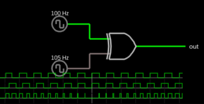
This is probably easier to visualize than read about. The Falstad simulator can show you a phase detecting XOR gate in your browser. Try changing the frequency from 105 Hz to other frequencies and observe the output. If you alter the frequencies to match while the simulation is running, you will probably still have a phase error. Try the Reset button to see what happens when the frequency and phase match.
The Low Road
Given a train of pulses, you can use an RC circuit to integrate the pulses (that is, develop a voltage proportional to the area under the pulses). This is a suitable voltage to feedback to the VCO. Depending on the VCO, you might need to process the voltage a bit, but that depends on exactly what circuit you are using.
There are other ways to do phase detection. For example, here’s another way to do it (see right). There’s probably plenty of other methods, too. The key idea is to compare the two frequencies and generate an output that can influence the VCO. When the phase (and, thus, the frequency) match, the output voltage will be stable at the level required to match the frequency.
So What?
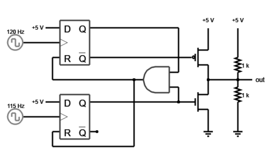
So far our PLL is a little underwhelming. It is hard to imagine why you wouldn’t just use the crystal oscillator. The magic happens when you change the output frequency in some way. For the most part, that means dividing the output frequency before the phase comparator. If you do that, the loop will lock the divided frequency to be the same as the crystal. That will produce a higher frequency at the output.
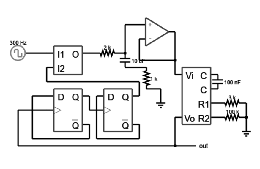
For example, above is a PLL that generates a frequency four times the reference oscillator. The two flip flops divide the output frequency by four, so the phase comparator locks the output frequency to 4X the reference frequency. Try changing the reference clock to, say, 10 Hz. Then try 100 Hz or 500 Hz. You’ll notice when you modify the clock it takes a bit for the loop to lock. For example, below is the output switching from a 10 Hz to 100 Hz reference (40 Hz to 400 Hz output).
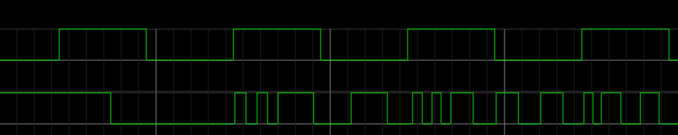
You can see the output jitters a bit before it settles down. Of course, dividing by four is just an example, you could divide by any number (often called a divide by N circuit) to produce different frequencies.
This scheme has a few advantages. First, the crystal oscillator can be a low frequency which is easier to build and make stable. If you have a programmable divider, you can generate many different output frequencies. However, you can’t just create any frequency you want. For example, suppose your reference frequency was 100 kHz. If you divide the output by 10, the output will be 1 MHz. If you divide by 9, you’ll get 900 kHz. Good luck trying to create 925 kHz.
One common solution to increase the frequencies you can create is to also divide the reference clock. This is often called a divide by N/M scheme. In the above example, suppose you could divide the reference clock by 1, 2, or 4. Now setting N to 10 you could produce 1 MHz, 500 kHz, or 250 kHz. Divide by 9 would result in 900 kHz, 450 kHz, and 225 kHz. You still can’t produce any arbitrary frequency, but you can get more frequencies. The 925 kHz you couldn’t do before? Just use M=4 and N=37. The reference frequency, then, is 25 kHz and 925/37 is 25. You can also think of it as dividing the output frequency by N/M to get the original reference frequency (925/(37/4))=100).
Uses
So far, you’ve seen a PLL essentially multiplying a reference clock by some integer factor. However, it can do more than just that. For example, PLLs can demodulate FM and AM (hint: the phase detector’s voltage output tells you how far off an FM signal is from the center). PLLs can also recover clocks from data, deskew clocks transmitted over long lines, and, using a lock-in amplifier, a PLL-like circuit can recover data from very noisy signals.
There’s plenty of details I’ve glossed over, and there are whole books written on the topic. However, if you want to explore more, [Jeri Ellsworth] and our own [Bil Herd] created a video on the subject you’ll enjoy (see below). There are many implementation options. You can create a PLL in software, even. If you want a one-chip solution, the CMOS 4046 IC comes to mind.


CMOS 4060 or 4046 ?
Oops typo that I will fix.
Video did a great job of breaking it down
Maybe a short discussion about the differences between frequency lock loops and phase lock loops would be good.
The one thing that has always confused me about the simple XOR phase detector — it shows you an error, but not in which direction.
If your crystal and your VCO are off by, say, 100 Hz, you can low pass filter that to get a useful value. However, you have no idea if the VCO is high or low by 100 Hz, so how would you know which way to push the VCO? Seems useless to me.
What you do is aim for a 180 degree phase shift – that is, half way between 0 degrees and 360 degrees. That way you get the directional cues. Because you’re right – when the phase shift is near 0 or 360 it becomes ambiguous which direction you should go.
No, if I remember correctly, your operating point has to be around 90° phase difference. With 0°/360° the output voltage of the EXOR will increase from near zero in any direction of phase shift. At 180° the output voltage is max. and will decrease in any direction of phase shift.
You’re right – 180 degrees instead of 360. Still, the high point is to shoot for the middle rather than the ends, which are ambiguous.
The light bulb moment for me with PLLs was when I was reading a very early spec sheet that showed that it was just a state machine with 8 (or 4) states. So then it was just a matter of seeing the transition triggers. Simple after that. I can’t seem to google the diagram though.
Old Grundig receivers (radio, TV etc) had a lot of PLL and varicap diodes in tuner stages.
I think the diagram you may recall is Figure 1 in the old Motorola MC14046B data sheet. This shows the state machine states clearly. I thnk this diagram was repeated in other Motorola PLL design and application notes but i have no reference for those
I’m using a 4046 in the latest iteration of my GPSDO (http://hackaday.io/project/6872-gps-disciplined-tcxo). Phase detector 3 is useful for this, as it will effectively time the difference between the GPS PPS rising edge and a divide-by-ten of the 10 MHz reference output. I use a diode+RC to turn the variable width (0-1µs) pulse into a voltage I check with the AVR’s ADC. The firmware takes this phase voltage as additional error information for the PLL.
Doing without this extra error information makes the GPSDO basically bounce around inside a 1 ppb corridor. The only other information you can have without the phase comparator is to count 10 MHz cycles between PPS intervals. That gives you an error granularity of 10 ppm per second, so to get a 1 ppb granularity requires sampling for 100 seconds. This makes the response quite slow, so the ADEV at moderate tau (10^1-10^3) suffers. Assuming you can get two additional orders of magnitude from the phase detector (that is, if the phase detector can scale to ±100 units), that means you can get that 1 ppb of granularity per second or 0.1 ppb in 10 seconds.
I’m still trying to dial the firmware in, but I hope to have something soon.
Be aware that the 4046 has a bit of deadtime in its phase detector. NXP fixed this in the 74HCT9046A.
Be aware that the 4046 has a bit of deadtime in its edge based phase detector. The 74HCT9046 fixes this but may be hard to get.
In my GPSDO application, it appears to be working properly, so it’s not a factor (so far as I can tell).
I just love this shit! Awesome
And PLLs live on! The recently released (and really nice) SI5351A is a PLL based multi-output oscillator par excellence.
Perfect, I need to understand this since I am trying to fix a Commodore 64 where the clock circuit is broken. This is a very old C-64 that uses discrete components as a PLL. Newer version has a much more integrated IC that does it all by itself.
In the above article, Al Williams gives a good overview of the 4046 and similar/derived parts.
(However, I wouldn’t waste a lot of time on Bill Herd’s video.)
There are a number of good manufacturer datasheets and ap notes out there. Particularly NXP, Fairchild, On, and TI. Some have more details on the part’s internals, others are better from a system perspective. So you’d do well to glance over several.
Several datasheets have the Phase Compartor State Diagrams, which may be interesting to study, but generally that much detail is not needed to understand the part.
————————
With regard to the Phase Comparators:
The EXOR phase comparator which is simpler, has several disadvantages.
When locked, the VCO will be 90-degrees from the input signal.
Care must be taken to prevent the EXOR comparator from locking onto a harmonic of the input signal.
The EXOR phase comparator is sensitive to the duty cycle of the input signals. (Ideally these should be square.)
An *advantage* of the EXOR, however, is that is has good noise rejection.
—————————-
The Charge-Pump phase comparator, being edge sensitive, has no input signal duty-cycle restrictions,.
However, it is *more* susceptible to signal input noise.
When in lock, the VCO will be at 0-degrees from the input signal.
This phase comparator will not lock onto harmonics.
And missing completely is the “steampunk” variant, analog PLLs.
They existed for a long time, but with tubes were too bulky for much use. The phase detector was a balanced mixer of some sort.
I’ve never seen a PLL in hobby magazines before 1957 or maybe 1958, when there was a synchronous detector described in “CQ” magazine. Then in the early sixties some articles about under the noise reception for things like moonbounce, though not necessarily described as PLLs. Ralph Burhan of VLF fame had an article in QST in 1964 that was an analog PLL, the control voltage following an FM signal, so FM could be demodulated, and a second balanced mixer for demodulating regular AM. That year the National HRO-500 receiver came out, using an analog PLL to lock a first oscillator to a 500KHz crystal to get signals every 500KHz, instead of a whole bunch of crystals. Analog phase detectors had limited lock-in range, so the VCO had to be tuned manually to get it within range
Then about 1970, Signetics introduced line of analog PLLs, lots of fun to play with, lots of SCA demodulators and FSK demodulators, and very simple AM radios. Really useful for signal detection and processing, not too useful for synthesis. But their existence was an excuse to describe PLLs, right at the time they could be useful.
Almost simultaneously frequency synthesizers started appearing in ham magazine. Both need and the availability of digital ICs combined. There was the MC4044P ttl phase detector, which was fancier than an XOR gate, so lock-in range was greater. Then of course the CD4046 cmos PLL from RCA, technically “cos/mos” they called it at the beginning, the choice of an XOR phase detector or something fancier. Suddenly there were frequency synthesizer projects, initially big steps, improving with time. Then slowly the transition to frequency synthesizers in radios.
Michael
Is it true? What if you control a VCO with the output of the phase detector via a voltage divider?
No, because of the feedback loop. The stable condition is when the two frequencies into the phase detector are equal. If you add a voltage divider, that will either mean you can’t lock (because the voltage after the divider is too low to move the VCO to the right frequency) or the loop changes in some way I can’t remember. An amplifier can certainly be part of the connection between the phase detector output and the VCO, but it affects other things, not frequency.
There are ways to change things. Make the reference frequency lower, so the steps can be smaller. But the lower it goes, the harder it is to filter the control voltage. You can generate a higher frequency and put a divider on the output of the VCO, outside the loop. That gives smaller steps, if you can live with a square wave.
You sometimes see a variant of this. If the VCO is running at a frequency too high for the programmable divider chain, you may have to put a fixed divider ahead of the programmable counter, which then makes the steps bigger (by the amount of the fixed divider) than the reference frequency.
You can put a mixer between the VCO and the phase detector, or the programmable divider. That moves the frequency by the a mount of the oscillator feeding the other input of the mixer. Make that oscillator variable in some form, and you can get frequencies in between “steps” (ie the frequency of the reference frequency). Of course, then the stability of this variable oscillator affects the stability of the PLL output.
Michael
How can I replace a crystal oscillator by a pll in an AM broadcast small transmitter (50 watts). I need to switch from 1620 khz to 1000 khz.
Why? When 1.000 MHz crystals are common and cheap