An Atomic Pendulum Clock Accurate Enough For CERN

That big grandfather clock in the library might be an impressive piece of mechanical ingenuity, and an even better example of fine cabinetry, but we’d expect that the accuracy of a pendulum timepiece would be limited to a sizable fraction of a minute per day. Unless, of course, you work at CERN and built  “the most accurate pendulum clock on the planet.”

While we’re in no position to judge [Daniel Valuch]’s claim, we’re certainly inclined to believe him, mainly because the 1950s-era Czechoslovakian pendulum clock his project was based on, the Elektročas HH3, was built specifically as a master clock for labs, power plants, and broadcast use. The pendulum of this mid-century beauty is made of the alloy invar, selected for its exceptionally low coefficient of thermal expansion. This ensures the pendulum doesn’t change length with temperature, but it still only brings the clock into the 0.1 second/day range.

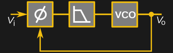
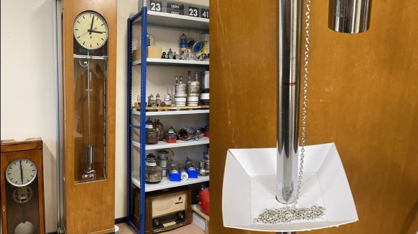
Clearly that’s not good enough for a clock at CERN, the European Laboratory for Nuclear Research, where [Daniel] works as an RF engineer. With access to a 10-MHz timebase from a cesium fountain atomic clock — no less a clock than the one that’s used to define the SI second, by the way — [Daniel] looked for ways to sync the clock up to it. Now, we know what you’re thinking — he must have used some kind of PLL to give an electromagnetic “kick” to the bob to trim the pendulum’s period. Good guess on the PLL, but the trimming method is a little cruder — [Daniel] uses a stepper motor attached to the clock’s frame to pay out or retract a length of fine chain into a cardboard dish attached to the pendulum’s rod. The change in mass changes the pendulum’s center of gravity, which changes its effective length, and allows the clock to be tuned a couple of seconds per day.

It seems like [Daniel] is claiming that his chain-corrected clock won’t drift more than a second from the cesium clock for 158 million years. Again, we’ll take his word for it, but it’s a wonderfully ad hoc approach to tuning the clock, and we appreciate its simplicity.

Split Flap Clock Keeps Time Thanks To Custom Frequency Converter

Why would anyone put as much effort into resurrecting a 1970s split-flap clock as [mitxela] did when he built this custom PLL frequency converter? We’re not sure, but we do like the results.

The clock is a recreation of the prop from the classic 1993 film, Groundhog Day, rigged to play nothing but “I Got You Babe” using the usual sound boards and such. But the interesting part was getting the clock mechanism keeping decent time. Sourced from the US, the clock wanted 120 VAC at 60 Hz rather than the 240 VAC, 50 Hz UK standard. The voltage difference could be easily handled, but the frequency mismatch left the clock running unacceptably slow.

That’s when [mitxela] went all in and designed a custom circuit to convert the 50 Hz mains to 60 Hz. What’s more, he decided to lock his synthesized waveform to the supply current, to take advantage of the long-term frequency control power producers are known for. The write-up goes into great detail about the design of the phase-locked loop (PLL), which uses an ATtiny85 to monitor the rising edge of the mains supply and generate the PWM signal that results in six cycles out for every five cycles in. The result is that the clock keeps decent time now, and he learned a little something too.

If the name [mitxela] seems familiar, it’s probably because we’ve featured many of his awesome builds before. From ludicrous-scale soldering to a thermal printer Polaroid to a Morse-to-USB keyboard, he’s always got something cool going on.

A Great Guide To Software PLLs

There are some things that you think you know quite well because you learned them in your youth and you understand their principles of operation. Then along comes a link in your morning feed that reminds you of the limits of your knowledge, and you realize that there is a whole new level of understanding to be reached.

Take Phase Locked Loops (PLLs) for example. You learn how they work, you use them for frequency synthesis, and you know they can do other things like recover noisy clock lines and do FM demodulation. But then you read [Paul Lutus’] Understanding Phase-Locked Loops page, and a whole new vista opens.

He’s discussing PLLs in the context of software, as part of a weather fax decoder project, and this allows a perspective that was unavailable to those of us who learned about them through the medium of hardware such as the venerable 4046 CMOS chip. We can easily look at different PLLs with varying parameters, for example their use with a narrowband loop filter to retrieve signals buried in the noise, all through some straightforward code tweaks rather than extensive circuitry. It’s a page that’s a few years old now, but resources like this one do not age.

If PLLs are entirely new to you then you need to reat last year’s excellent PLL primer by Hackaday’s own [Al Williams].

[via Hacker News]

[PLL diagram: Chetvorno CC0]

Unlock The Phase Locked Loop

If you want a stable oscillator, you usually think of using a crystal. The piezoelectric qualities of quartz means that it can be cut in a particular way that it will oscillate at a very precise frequency. If you present a constant load and keep the temperature stable, a crystal oscillator will maintain its frequency better than most other options.

There are downsides to crystals, though. As you might expect, because crystals are so stable it’s hard to change the frequency much when you want a different one. You can use a trimming capacitor to pull the frequency a little, but to really change frequency, you have to change crystals.

There are other kinds of oscillators that are more frequency agile. However, they aren’t usually as stable. To combine flexibility with crystal-like stability, you can use a Phase Locked Loop (PLL). Many modern systems use direct digital synthesis, but the PLL is a venerable and time-tested technique.

Continue reading “Unlock The Phase Locked Loop”

Logic Noise: 4046 Voltage-Controlled Oscillator, Part One

In this session of Logic Noise, we’ll be playing around with the voltage-controlled oscillator from a 4046 phase-locked loop chip, and using it to make “musical” pitches. It’s a lot of bang for the buck, and sets us on the path toward much more interesting circuits in the future. So watch the intro video right after the break, and we’ll dig straight in.

Continue reading “Logic Noise: 4046 Voltage-Controlled Oscillator, Part One”

Intro To Phase-Locked Loops

[Kenneth Finnegan] put up a lengthy primer on PLLs (Phase-Locked Loops). We really enjoyed his presentation (even the part where he panders to Rigol for a free scope… sign us up for one of those too). The concepts behind a PLL are not hard to understand, and [Kenneth] managed to come up with a handful of different demonstrations that really help to drive each point home.

A PLL is made up of three parts: a phase detector, a low pass filter, and a voltage controlled oscillator. It can do really neat things, like multiply clock speed (you see them in beefier chips like the ARM architecture all the time). The experiments seen in the video use a CD4046 chip which has two different types of phase detectors. The two signals displayed on the oscilloscope above compare the incoming clock signal with the output from the VCO. Depending on the type of phase detector used, and the quality of the low-pass filter, these might be tightly synchronized or wildly unstable. Find out why by watching the video embedded after the break.

Continue reading “Intro To Phase-Locked Loops”