I’ve had a few conversations over the years with people about the future of 3D printing. One of the topics that arises frequently is the slicer, the software that turns a 3D model into paths for a 3D printer. I thought it would be a good idea to visualize what slicing, and by extension 3D printing, could be. I’ve always been a proponent of just building something, but sometimes it’s very easy to keep polishing the solution we have now rather than looking for and imagining the solutions that could be. Many of the things I’ll mention have been worked on or solved in one context or another, but not blended into a cohesive package.
I believe that fused deposition modelling (FDM), which is the cheapest and most common technology, can produce parts superior to other production techniques if treated properly. It should be possible to produce parts that handle forces in unique ways such that machining, molding, sintering, and other commonly implemented methods will have a hard time competing with in many applications.
Re-envisioning the slicer is no small task, so I’m going to tackle it in three articles. Part One, here, will cover the improvements yet to be had with the 2D and layer height model of slicing. It is the first and most accessible avenue for improvement in slicing technologies. It will require new software to be written but does not dramatically affect the current construction of 3D printers today. It should translate to every printer currently operating without even a firmware change.
Part Two will involve making mechanical changes to the printer: multiple materials, temperatures, and nozzle sizes at least. The slicer will need to work with the printer’s new capabilities to take full advantage of them.
Finally, in Part Three, we’ll consider adding more axes. A five axis 3D printer with advanced software, differing nozzle geometries, and multi material capabilities will be able to produce parts of significantly reduced weight while incorporating internal features exceeding our current composites in many ways. Five axis paths begin to allow for weaving techniques and advanced “grain” in the layers put down by the 3D printer.
Part One: Improving What We’ve Got
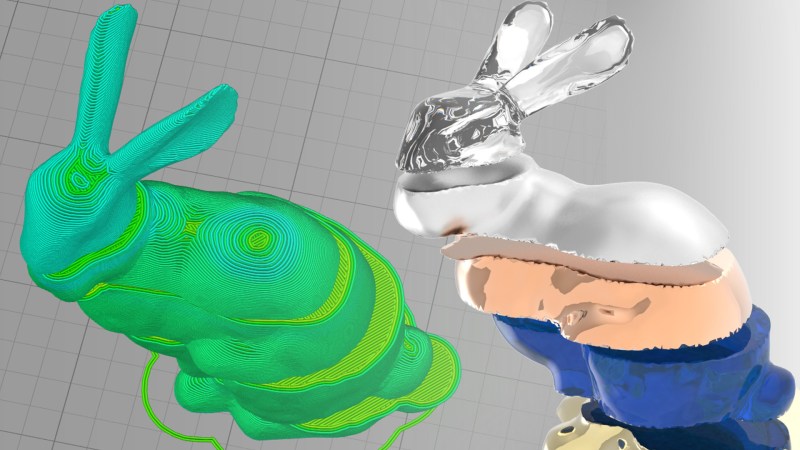
The current goal of a slicer is to take a model and render it as geometrically accurately as possible. The slicer doesn’t care about the strength of the part, or know its place in an assembly. It simply tries to produce an outer manifold surface that matches the original as closely as it can. It does this by slicing the model into layers and then drawing 2D paths within that layer via a filling algorithm. There’s more to it than that, but for the most part it disregards the design intent completely. Instead, it checks for failure points in the 3D printing process by moving up and down a layer during its generation stage. If the exterior of the resulting shape matches the input file, the slicer is happy.
Telling the Software Why It’s Making
To really begin to get the most out of simple 3D Cartesian printing, we must tell our software not about the geometry of our part, but its design intent. If we can give the slicer information about how the part will be used in the future, it can begin to optimize the paths and infills it chooses. For example, a surface which will act as a cam or gear tooth needs multiple perimeters of plastic and more infill behind those layers. Mechanically, the gear won’t need a lot of infill between the teeth and the hub, but the hub will probably need more infill and layers.
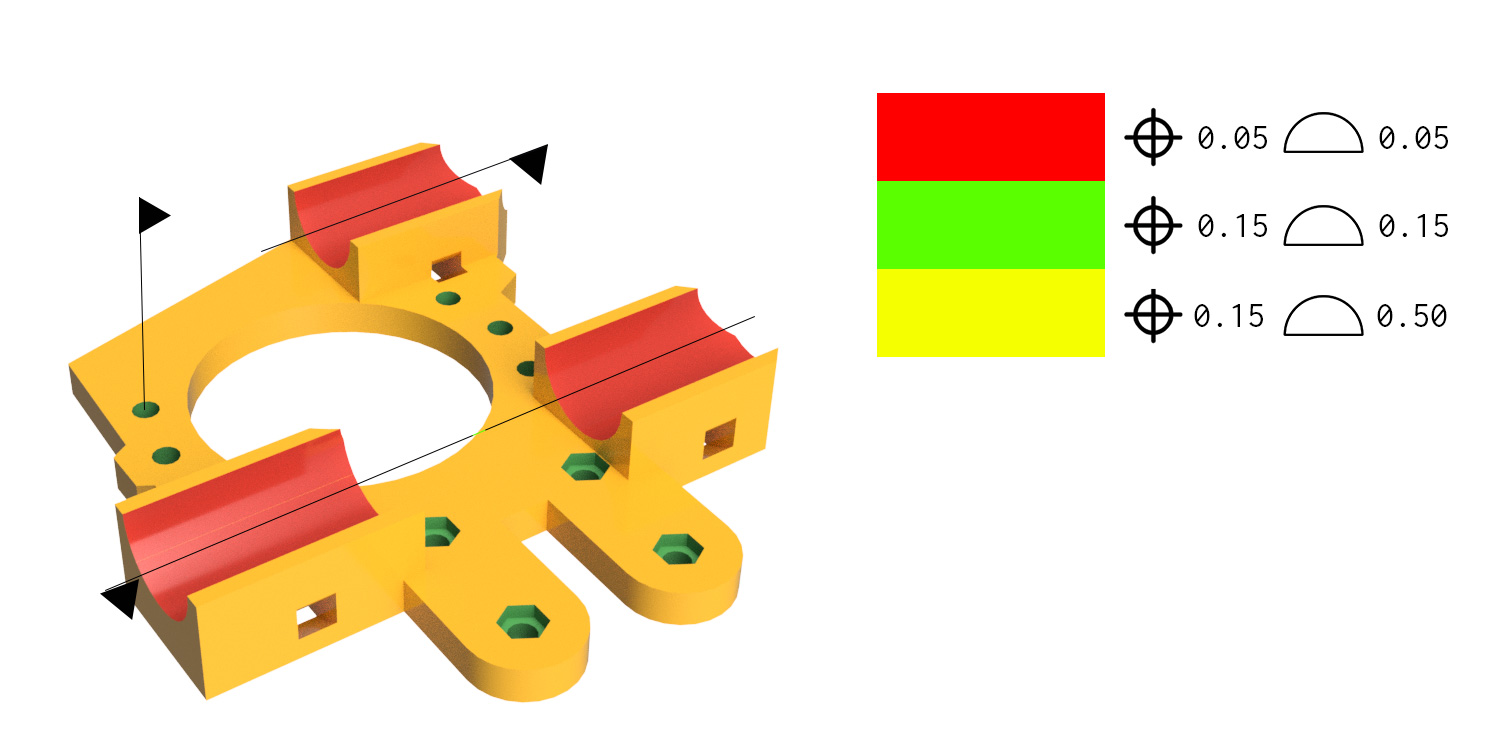
Another useful set of instructions to give to the software is the dimensions and tolerances of the part. The industry standard for this worldwide is GD&T. How many times have you printed a part with a slot and key only to find that they do not slide together as intended? A corner with too much plastic, or a blob where the printer chose to start the layer blocking a good mechanical fit. With GD&T communicated to the slicer, it can know useful things like, this tower is decorative, but this cylinder is a shaft and needs to be within .25 mm or it wont fit. That way the printer can slow down on the shaft or even incorporate dwell times to make extra certain that all the dimensions are accurate.
One way to do it, a new software interface.
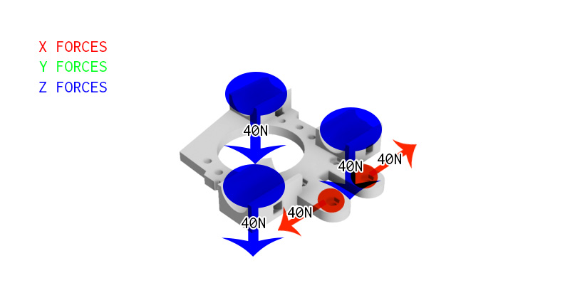
So how will we enter the forces on something into the software? One solution is the strict engineering one: a person would select a hole and then say it will receive ten lbs of force parallel to an axis. Or that the GD&T is rigidly and properly defined as if were sitting on a granite plate.
There are easier ways, too. For example, a person could use a software very much like Z-brush. The person could then paint a “heatmap” of expected forces on the model. This wouldn’t necessarily communicate the same useful information as the engineering version, but it could allow the slicer to automatically determine the thickness of the walls at that location.
The same “heatmap” technique could be used to indicate surfaces of increased geometrical accuracy. A person could paint on “high precision” or “+-.05”mm. In these areas the printer may choose to implement a higher layer height resolution or slow down significantly to reduce acceleration-induced artifacts in the final print. It will lack information such as the positional relationship between holes and the tolerance stack, but for the most part it will serve.
The hard engineering approach does have its advantages. Especially when it comes to assemblies. You could tell the software that a stepper motor is going to transmit 80N of force into one hole on the part and have the software determine the rest of the experienced forces for the assembly from that, automatically optimizing the part as it went a long. The hard engineering approach will also have additional benefits in later chapter when we begin to examine some of the potential in multi-material and axis printing.
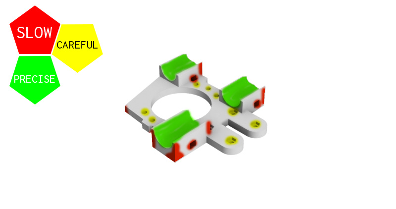
Finally, the “heatmap” technique can be used within the slicer to indicate areas you would like the slicing to pay extra attention to. I think this is the most quickly implemented strategy. It is most similar to the one for applying tolerances, but it is just an easy way for a user to tell the printer to slow down in areas or dynamically adjust the layer height. For example, should you print once and find the printer has absolutely wrecked an important corner, simply open up the slicer and paint that corner with the color for detail. The slicer will then slow down and take its time around those corners to produce a more accurate section.
FEA integration for the computationally inclined.
It was touched on in the earlier section, but once design intent starting being communicated to the slicer, [finite element analysis](https://en.wikipedia.org/wiki/Finite_element_method) (FEA) could be used to help generate advanced paths.
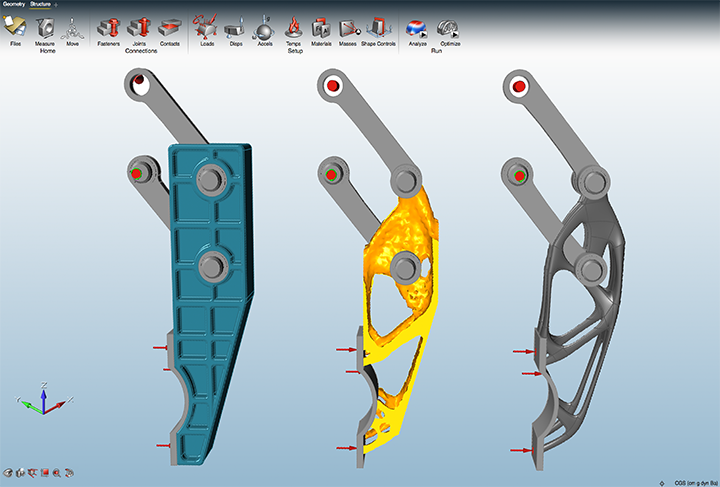
There are a few commercial solutions out there that offer similar capabilities for parts that are machined or cast. FDM 3D printers have an advantage over SLA and SLS printers in this arena too. Only FDM can create hollow sections within a manifold volume. SLS and SLA printer can benefit more from solutions like Solidthinking’s to the right.
On the simplest level, infill and layer densities can be increased in areas of the print’s internal volume to increase strength. There’s no reason that a post which experiences a significant load can’t have solid infill closest to the load, and fan out to sparser infill as the forces dissipate. The printer could also do things like dwell time on areas of stress concentration to force a stronger layer bond.
The slicer could also generate paths that have grain in the correct orientation for the loads the part will be seeing. I’ve had a few parts fail because I didn’t have the part rotated correctly for the rings of the 3D print to resist the forces correctly. With FEA capability, the slicer could simulate the load on the part and then try it in different orientations until the layer seams no longer cause a failure.
Once you get started on the additional possibilities this provides, it’s hard to stop.
The Next Logical Step, a Shiny New File Format
There are no commonly accepted file formats in use today that communicate design intent. As mentioned before, if the Open Source community were to band together, or if an open source company could oversee the creation of such a format, they would be leading the world. The format should be able to communicate a few critical things.
- Manufacturing Method: SLA, SLS, FDM, Injection Molding, Stamping, Turning, Machining, etc. Including this information will help future software automate its approach to the geometry and simulation.
- Dimensions and Tolerances: Using GD&T the file should contain all the information necessary to produce a 2D or 3D drawing for manufacture and inspection. Software will use this to automatically tune CAM generation for the manufacturing method.
- Design Intent, Features: There are very standard things in machine design such as hole, weldment, live hinge, composite layers, CAM surface, etc. Telling the software that this is a hole and it has a tolerance is important.
- Design Intent, Forces: Either define the forces that the part will see or define another part in the assembly that will transmit forces to it.
- Design Intent, Assembly: Which parts link to the file? Not only will this allow for simulation, but it will let the computer check the tolerance stack and find problems with fit.
- Design Intent, Composite: Is the part made of two plastics? How can one file define the two colored tree frog example? Or a R/C car wheel with a stiff inner part and flexible outer?
- Design Intent, Materials: What materials are the part expected to be made of? Especially with multi-material printing this will be important. It also lets the software simulate with minimal configuration.
- Parametric geometry data: A data file that stores the geometry in as generational a format as possible rather than rigid polygons that must be scaled or subdivided. OpenSCAD, Soldiworks, Inventor, and others work this way. They calculate the geometry, rather than storing it.
- Extensibility. It would be nice to start out with a simple, text-editable container format as the core. This would also avoid the need to write the whole format all at once.
- Standard Libraries: The format should always contain the latest material definitions, but it should have the ability for self updating. If Taulman wants to host a repository of data about its filament, the software should be able to find the latest version and update.
Printer to Slicer Calibration:
One major issue with slicers today is that they very much reflect the hodgepodge evolutionary nature of 3D printing. The values entered into a slicer to determine print speeds and feeds have very little to do with the actual mechanics and dynamics of extruding a plastic for a nozzle. Rather than a volume-in, volume-out determination based on the configuration you have, these programs rely on you to adjust to an expected result by printing a geometry, measuring it, and arbitrarily changing multipliers until the geometry printed matches the geometry expected. While at face value this seems to be a good and cogent solution, it instead results in prints that have too little infill, or excess plastic in odd edgecases. Better understanding of nozzle pressures, geometries, and filament properties will allow us to calibrate our software better.
Part 1 Conclusion
In the end these are just my thoughts about the future. Fused Deposition Modeling has been around since the 80s. However, in 36 years, its core technology hasn’t improved much at all. I’ve used the industrial systems and they work with layers, infill, and perimeters too. In fact, in many ways they’re worse and harder to use than the open source solutions out now.
At least in terms of the software, 3D manufacturing is way behind other fields. My favorite example of where we should be heading is gaming. Video games have incredible tools — tools that put the best solid modelers and the best simulators in 3D printing to absolute shame. Some companies like Autodesk are starting to push new boundaries, but for the most part the field is moving at a snail’s pace. Incremental progress is great, but it’s always good to envision the future. Maybe we’ll start to realize what we don’t have, and get the urge to build it.
Edit: After a discussion with [Rev Tactule] in the comments I thought it would be best to make a small edit. Just to be clear, most of the ideas I am talking about here are actually quite old in the industry. Lots of work on this has already been done, and is being done in the commonly used open source projects. Not to mention, the big three, Autodesk, Siemens, and Dassault all have their own GD&T container format and accompanying software to do tolerance stacks as well as software assisted design, simulation, and manufacturing. They’re just hard to use and proprietary.
Heck, the ISO 10303 specification started in 1984, for the STEP format, has provisions written into it for everything I’ve mentioned. Just no one uses those features. Keep in mind that’s in 1984, which means that all the stuff I’ve mentioned has been in use in some form or another since the 70’s. (Maybe the right path is just to start using STEP?) Some of what I’ve said is perhaps new, but not startlingly so, and anyone who knows the field and history could easily come up with a similar expression of these technologies in a little time.
My goal here is to compile all the commonly known techniques in the industry into one possible cohesive vision of what we could have in the future as far as slicing and 3d printing goes. Lots of people have already done an amazing amount of work on this stuff, as [Rev] pointed out. Just check the comments for [Rev], [Joshua Elsdon], and [Dan#9445376854 ] for examples of the incredible amount of work that is going into it all. My hope is not to lay claim to or steal credit from. (The comments are a great place to brag, btw) It is simply to get more people thinking, and, hopefully, dissatisfied with what they have. Dissatisfaction breeds innovation after all:)


Or, just grab a tube of superglue and feed your slicer output into a laser cutter.
I am sorry but I just flat out disagree with your opinion that fused deposition modelling (FDM) can produce parts superior to other production techniques if treated properly.
Superior for what application and in what way? How is FDM, a point based build process, faster than exposing an entire layer at once? You cannot even make a perfect square with it and it’s a continuous process. You cannot even stop arbitrarily and then resume with it. Yes, there are techniques to minimize these issues but the resolution is limited, it takes a long time to build, certain geometries are impossible and you are limited to only a few materials that are constantly off gassing somewhat toxic, almost burning plastic fumes. Solid geometry parts are also significantly more resource intensive to produce.
I believe what [Gerrit] is pointing at the the possible benefits. With only tweaking the G-Code you could print a part with variable density, and alternating the layer directions to change the grain (for lack of a better term) of the print. With dual extruders you can combine different material properties and more. There are pro’s and con’s to every type of 3-D printing, and this article is trying to point out some of the ways to improve FDM which makes sense since it is usually the cheapest and probably the most common type of printer.
Slicers already alternate the grain on the infill. They travel the opposite way. One small improvement that could be made is to stop using angles for the infill and use straight 90° sections. On a Cartesian printer this means only one axis is active at a time, which reduces vibration and stepping errors. Another improvement that I seek is changing the layer height for the top layers. If I print the part at 200 um, I’d like the top layers to be at 50 um. This dramatically improves the top layer resolution and also produces a much more dimensionally accurate print. The top layers on most 3D printers has historically been too high because it’s hard to predict the final height of an object when errors compound to the final layers.
the printers may be cheap but the actual printing is several times that of laser sintering, many more if one uses the expensive “made to purpose” filaments that many hobby users seem to use.
so both the material and processing is more expensive while the machine is far cheaper.
While I agree that FDM isn’t superior in all ways. I have to tell you 1 bit. Toxic gasses? Not actually happening. We had a specialized company measure this for us in our 20 printer ABS room. No problems there for health.
Pretty much no problems anywhere in our company, until someone used the hairspray method to prepare a bed. That’s when the measurements went trough the roof. Like 100x over the limit.
We still print ABS in dedicated rooms, but that’s mostly because it does smell.
Compared to resin based printing, the material options are huge. Options for tweaking are much higher, could do a low res print in 2 hours with a 0.8 nozzle, or the same print in super quality in 20 hours with a 0.25. All with the same machine. Software chains are much more advanced right now.
And, the raw material isn’t a toxic chemical that will build up to a slowly but surely allergy. Nobody seems to tell you this, but I’ve spoken to people who where in the resin printer business for years already before this whole 3D printing hype started. They are quite shocked how irresponsible people are with these UV resins.
Resin printing does give a super amount of details and nice finish. We use it for certain prototypes as well.
(I work for Ultimaker. Cura guy)
Screw toxic resins, laser sintering gives you an incredibly wide array of usable material and produces mechanically superior parts, since they can be even actual metal. Only problem is the cost for the laser itself and the rastering optics.
Maybe because most of us can actually afford to do it? That sure makes it the superior method for me!
FEA aware slicers sound like a great idea. It may make sense to break models into pieces to optimize grain direction for different surfaces, then solvent-weld the pieces together.
I think that building a multi-grain orientation part is one of the reasons that a theoretical 5-axis FDM printer was mentioned. On printers with an enclosure, I could see lots of use for a “sintering and densification” step after the print finished. A “strain relief” cycle may be useful as well.
One thing that bothers me about going via STL is that it introduces facets to the part. A friend built a DLP printer and I wrote a slicer that runs inside Autodesk Inventor that slices the native geometry creating a multu-layer SVG file with all curves rendered as curves. https://www.youtube.com/watch?v=hefY46fyVvU
It ought to be possible to port the concept to Autodesk Fusion (which has the great advantage of being free).
STL is very much a lowest common denominator format, with very few features. Getting a high fidelity surface in STL may require a very high polygon count in a large file. But it has very wide support among both geometry creation and slicer software. Whatever you use to generate geometry is independent of the printer.
Going the other direction, a slicer to support a more full featured geometry format, like CAD, still has to support the particular demands of whatever printer you use. If the plugin for your chosen CAD software doesn’t support slicing compatible with your printer you’re out of luck. If sending your design out to be printed, the printer may support a limited number of formats.
I see the real problem with STL is in the iterative process of prototyping. If you could take your STL part, mark the requirements of the surfaces (tolerance, thickness, etc), then print it – if you change your design, your triangles move, not just in position, but the triangulation of the surface . Proper CAD formats have better abilities to remember these attributes.
That’s the hook though. It’s only free for students, enthusiasts, hobbyists, and startups.
Otherwise it starts at $25/month. Free trial though.
It’s also cloud based, so you don’t actually own any of it and you cannot ensure it will always work or always work with the files you previously created. It also requires internet access. It’s a closed binary blob, but worse.
No, thank you.
That’s what I was thinking the whole time reading the article – nice ideas, but right now I’d much appreciate if we had a properly usable and powerful open source CAD package. Between Blender (good luck with the UI – you’ll bloody well need it), OpenSCAD (I much prefer to manipulate thing visually thank you very much), FreeCAD (always improving but somehow perpetually never quite usable) or SolveSpace (still the most usable of the bunch but clearly has its limits) everybody ultimately seems to end up using Fusion, Sketchup, Solidworks or something similarly not-really-free and proprietary “here now gone tomorrow” package. Seeing the entire field just give up and rally around corporate solutions annoys me immeasurably. Unfortunately, I have no better idea either of how to get away from that…
Max, you should give Onshape a try… It sits just in between all you’ve mentioned and quite maker friendly.
Thanks for the suggestion, and would – except I had no choice but flee as soon as I bumped into “cloud-based”.
To put it bluntly: let me own the code, or stop wasting my time.
You forgot the most-industry-tested open-source package: BRL-CAD. I’ve been wrapping some of the their modelling functionality into a Python API and so far I’m having a great time! This software has literally been bullet-tested!
you can sorta do this already with slic3r and modifier meshes, see more here: http://slic3r.org/blog/modifier-meshes
But that said, I’ve never gotten it to work, and usually just print with the maximum infill and minimal speeds required to get a good print, or fix things with a file after if its too fast.
Gerrit, I mentioned GD&T to you in a comment previously on 3D printing. Thanks for crediting your readers for the ideas in your article.
http://hackaday.com/2016/03/07/its-time-the-software-guys-and-mechanical-guys-sat-down-and-had-a-talk/#comment-2947435
Very cool. I missed that comment previously. Obviously, I agree with your stance 100%, and it’s gratifying to see that there are other engineers arriving at the same point from different paths. It adds validity and demonstrable need to the idea.
Yes much is needed for this idea. But before you write an article about the “Future of Slicing” you should take a good hard look at the present beyond your immediate experience and what you think may be better. Look at the github sources for slic3r and Cura. People have been writing and thinking about the points you bring up and for you not to cite them does disservice to them and your article.
The big three, Autodesk, Siemens, and Dassault all have their own GD&T container format and accompanying software to do tolerance stacks as well as software assisted design, simulation, and manufacturing. They’re just hard to use and proprietary.
Heck, the ISO 10303 specification started in 1984, for the STEP format, has provisions written into it for everything I’ve mentioned. Just no one uses those features. Keep in mind that’s in 1984, which means that all the stuff I’ve mentioned has been in use in some form or another since the 70’s. (Maybe the right path is just to start using STEP?)
Anyway, while I can see your point, I have to disagree, I hope we can remain amicable regardless. I don’t think I’ve done them a disservice by not looking for or citing their, relatively, recent work when these ideas have been in use and being developed since the 80’s and earlier (aerospace has been doing this stuff forever). I’m glad there is work being done, I’m glad they are being translated to 3d printing. I’m not laying claim to any of it. As far as I’m concerned, the techniques and technologies as well as their combinations are common industry knowledge, and obvious next evolutions to anyone with experience in the field as proven by, as stated in our conversation, many people already working on it.
OK fair enough. I usually see HaD articles very well cite their sources. Your last “look into the future” was fiction and I had to believe that what you wrote here was written as your invention (from your perspective) as well. I think what you just mentioned here, the facts and standards cited would have added depth to your thoughts. I think if any file standards originate in the hacker circles they would cite this article as well, FWIW.
I’ve made an edit to the article after thinking on your last post. I hope it is acceptable, and I will try to think of ways to be more clear in the future.
Hello,
Interesting article, it might interest people that I made a demonstration of 5 axis printing a couple of years ago. It used a 3DR delta with add on rotational stages. Check out the video here -> https://www.youtube.com/watch?v=-b5bFNYjSRk I found that the parts were much stronger than a comparable part printed traditionally, in fact a short ‘upright’ bar was printed traditionally (25% fill), Solid (100% fill) and using the 5 axis technique (25% fill). The 5 axis part was considerably stronger than even the solid part. I can send my report to anyone that is interested, I would rather not post it publicly.
nice concept :)
This was a very well articulated article that I found quite intriguing. More than that, it seems Gerrit has several legitimate points. While I abhor the flagrant overuse and reprehensible misuse of XML, an XML file format would be the ideal format for something that you want to be fully extendable in unexpected ways, human readable and system agnostic.
That’s one of my biggest frustrations with 3D printing: specifying the infill and the wall thicknesses. Unless I specify it exactly (and end up with a 190 MB file, like one I did a couple of weeks ago), the slicer usually generates a bad compromise, wasting material and time, or making a part that’s too weak in some important spot.
A really cool everyday example of “optimal” infill and wall thickness is trabecular bone (“marrow”) and in particular how it transitions to hard, dense cortical bone at the joints and at the bone surface, where it matters. What’s neat is the density of the trabeculae (and average density of the bone) is higher where there is greater load. Grows that way, almost like an evolutionary algorithm…
Look out for Hyperworks/Hypermesh. Commercial, good results, many types of loadcases, optimization targets, glitchy gui and exporting meshes is a bit emberassing.
i know i had a print for an adapter to put a square peg in a round hole (dont ask) several times because there was no way to say print the 5mm near the joint between the socket and the peg solid. i ended up printing the peg manually filled with a hexagonal subtractions to prevent material wastage, then printed the whole thing solid. it was the second longest print ive ever done (the longest was the case for the printer’s psu).
“At least in terms of the software, 3D manufacturing is way behind other fields.”
I have heard this so many times….
Software guys: “it’s hardware, it should be able to do that”.
Hardware guys: “i am sure that can be fixed in software after”.
IC guys: “i am sure we will fix that with the surrounding HW/SH”.
X guys: “to get that working we will just have the HW guys make some HW and run some SW on it”.
that = multidisciplinary complicated problem that everyone things it should be simple to solve outside of their field.
This sort of misses the issues with consumer 3D printing, and I am not sure the stated application of FEA strictly makes sense.
The big issue with ‘consumer 3D printers’ is that they simply are fake. They are not actually meant to be consumer 3D printers, they are something else. Something closer to those low end fake stereos that look real to laypeople but are just terrible in reality.
What good is this dynamic changes in treatment of certain areas of a print if that print will never print the same twice regardless?
Its fine for SOME hobbyists, the quality, but it simply is a huge time sink for most of us who are actual 3D designers.
You can achieve a very rapid but useful level of internal structural optimisation by using 2D image operations on slices, that can be run on a GPU and are therefore are very rapid. The resulting map is used to guide the parameters of contours and or cell sizes. i.e. darker means smaller cells therefore greater local density of plastic.
See this rough example http://i.imgur.com/46ocE1C.png
Let me know if you need advice as to what filter sequences to use. They are all part of G’MIC but the end code would ideally be custom and aimed at GPUs.
CC BY-NC-SA (with credit going to HaD community)
https://licensebuttons.net/l/by-nc-sa/3.0/88×31.png
For an example of how the above map could be used see http://through-the-interface.typepad.com/through_the_interface/2012/02/sphere-packing-in-autocad-filling-an-arbitrary-solid-using-net.html In this case the map adds to the size weighting for the packed spheres so you get the best of both worlds, the strongest possible cells with the best distribution and sizing of the cells. The would be an overall variable that lets you trade of total part weight against strength with individual spherical voids getting smaller as the strength goes up.
While a sphere is simple, it’s likely to create overhangs inside the part that can’t be printed. Maybe choose some other regular solid? (like an Octohedron?)
There is no reason to think that this is correct, why would small spheres have an overhang that was unprintable. Isn’t the key variable the size and you can control that? Why introduce a shape with corners and edges when they facilitate crack propagation?
I’d be interested in Daid’s take on this. Ever since he got new software colleagues(underlings) the development process of Cura seems to have stalled. What’s up man with that man?
Good to see you’re still up to your good old insulting undertones.
Have you even bothered to look at the Cura repositories? If you did, you would have seen that there are tons of changes and improvements, with a new version comming up in about a week.
But yeah, don’t listen to me. I’m just an “underling”.
How about 3D printing that’s actually done in three dimensions instead of a stack of 2D layers? For example, model a vertical tube then ‘push’ down on two sides to make the top and bottom ends have a sinusoidal shape.
To print that, first build a support scaffold in traditional stacked 2D fashion. Then print the part by following the shape of the support’s top around and up and down.
The finished part should be much stronger, especially on the projecting bits of the ends, due to not having any flat planes between the print layers.
The amount of slope that could be made would depend on the shape of the extrusion head. Those dimensions would have to be put into the slicer so it could come up with a path that doesn’t collide part of the printer into the item being printed.
This type of operation could also be incorporated into prints that have flat bottoms and tops. Slightly vary the layer height to ‘wobble’ the printed structure up and down, gradually increasing the wave height as the print rises above the build plate then gradually decreasing as the top is neared, finishing up with a flat layer. Not only would this make the perimeters less prone to splitting along layer lines, it should do good things for improving infill strength.
Having wavy layer lines on the outer surfaces may even make filling and finishing easier since there’d be no dead straight lines that are hard to cover up with filler. No matter which way you’d run sandpaper, it would always be moving at some angle to the layer lines.
“Oh sure, Video games can use all the cores in my computer plus my graphics card to do live physics but 15fps is standard for CAD.”
That’s because the game isn’t simulating physics – it’s simply trying to look like it’s doing it and doesn’t care if it goes subtly wrong – nobody’s going to know the difference. The CAD software is doing actual FEM computation instead of moving pre-defined breakpoints and joints around.
Some games use real physics engines from various start-ups. These do accurately model moving masses (fairly) accurately. They obviously relax the accuracy requirements to make it good enough for games, but there are high accuracy versions of these too. Some open source. Wikipedia has a nice summary (https://en.wikipedia.org/wiki/Physics_engine). Some are open source and may be a starting point for a higher level view of slicing.
You should read more about that Beam game in the article, the one that crash gif is taken from. It’s not just using pre-defined breakpoints and joints. It’s doing soft-body deformation and modeling the strength of attachment points.
I don’t think FEA is as plug and play as you seem to think it is. It takes a lot of thought and effort to get the constraints and loads to simulate reality. In addition you need to perform testing to assure your models match reality. There’s a lot of trial and error. Its not nearly as simple as saying 10 lbs on this surface and calling it a day.
As far as I can tell it is a nearly non-sensical understanding of what FEA is.
Maybe they mean in some broader sense as in, but it just seems like buzzword mangling to me too.
What you describe is also only one aspect of Finite Element Analysis.. Think about what these words mean.
For a long time now, I’ve wondered why slicers can’t generate gcode that makes a printer lay down contoured lines in the Z-axis. Example; you’ve got a shape that ends in a curved top surface, instead of laying down a bunch of stepped lines and making it look like ass, why doesn’t it print the walls first, and then lay curved strands of filament across the top? I mean, it’s a CNC machine…it just happens to have an additive tool instead of a subtractive one! Make it behave like a CNC mill contouring a complex part.
On literally every print that isn’t strictly mechanical, I drive myself nuts trying to find a solution to get the best finish on all surfaces. :(