[Limpkin] has an idea for a project that uses a lot of IN-9 Nixie tubes. Where a Nixie tube clock would only use four or six tubes, [Limpkin] is looking at fifty IN-9 bar graph Nixie tubes. These tubes only light up above 100 Volts and draw about half an amp. That’s 64 Watts, according to the math on the project page, so how does [Limpkin] plan on powering these tubes? With a big high voltage power supply.
The power supply [Limpkin] designed is more or less what you would expect to find in any power supply. There’s a transformer, a bunch of caps, and a rectifier. Going with a standard laminated core transformer would mean this power supply would be huge and heavy, but once again eBay comes to the rescue with a small, 150 Watt toroidal transformer. The largest output on the transformer was two 24 V outputs. Combining those outputs gets [Limpkin] to 48V AC, or 68V peak to peak. A full wave voltage doubler with two caps and two diodes gives [Limpkin] the 136V DC that will power the tubes.
Combine the high voltage circuit with a 9V AC tap, a small bridge rectifier, and a few more caps, and [Limpkin] had a supply that would power the tubes and the rest of the electronics in his multiple Nixie tube project. A few passes with a CNC mill gave the power supply a nice case topped off with a foreboding toroidal transformer ready to power a beautiful neon project.


No bleeder resistor? The extra five cents is well worth it.
His project log suggest something more clever!
I’d still feel safer with a bleeder resistor discharging it in deterministic time!
Just resist the urge to lick the terminals and you’ll be fine.
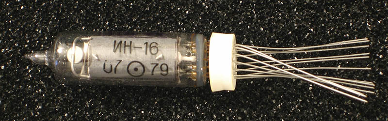
IN-9 tubes aren’t Nixies, because ‘Nixie’ is a trademark that was originally an abbreviation for ‘Numerical indicator experiment’. Since IN-9 tubes don’t display numerals – and the IN-9 tubes were not made by Burroughs Corporation, holder of the Nixie trademark – using the word Nixie is completely incorrect. I wish these ‘reporters’ would report on things and not just make stuff up. I’m done with Hackaday and I hope the author dies in a fire. Also, there are numerous gramattical errors in this post. What is ‘a lot’? it’s ‘alot’. Hackaday needs an editor.
“gramattical” he says. ;)
And thinks “alot” is a word. ;)
HEY! You the same localroger that wrote Metamorphosis of Prime Intellect? Haven’t seen you around since K5 imploded.I’m still recommending that story/novel to people interested in hard scifi/horror :)
All the best, J-
It’s part of the hackaday trademark.
offer an alternative. i propose Neat Instant Xenophilic Integrated Emitter tubes…
IN-9 tubes are sold in cases of 50 pieces, so one case is a “lot” of tubes. HaD writers are so dumb they don’t even know when they get it right!
Just kidding, I think a case of IN-9 is 100 pieces.
I laughed.
In Top story in tomorrow’s Hackaday; Benchoof fires Benchoof.
This would have been a great april fools post
Oof!
The Nixie tube is what you would call a genericized trademark.. these were legally protected trademarks, and have lost their legal status due to becoming generic terms.
You do the same thing every day without thing about it.
E.g.
Had a headache; did you take a Asprin?
Was it a Bayer branded tablet or was it generic ASA.
I guess there are no people who are addicted to Heroin; that’s another Bayer trademark and I’m pretty sure they aren’t selling it on the street.
Ride Escalators?.. was it built by the Otis corporation or was it actually a mechanical moving Stair case.
I guess I have never seen a Laundromat by you reasoning since that is a Westinghouse trademark.
A few more courtesy wikipedia
Own a Thermos?
Jump on a Trampoline?
Ever owned a or watched a Videotape?
Originally trademarked by Ampex Corporation,[19] an early manufacturer of audio and video tape recorders.
No hard feelings though and if we ever cross paths IRL i’ll buy you a Coke
Pepsi ok?
There is also Kleenex…
Another one is a “Bridgeport” which has become a generic term for a vertical turret knee mill.
What is a ‘videotape’?
JK I used to record LOST because waiting two days for it to show up on demand was too long a wait!
gramattical
Videotape? betamax is where is at
All of the world’s 4×4 vehicles are “Jeeps”…
Brian, why are you so based?
I thought he was rather acidic.
Back to /b/ where you belong.
Well that escalated quickly.
I mean, there’s REAL NEWS being misreported out there, stories being suppressed by corporate entities, people dying to bring stories to light. But you chose to complain that an old trademark wasn’t properly used.
Pull your panties from out of your crack. Tin foil. Duck tape. Band aids when the box clearly says ‘adhesive bandages’. Find something else to b!tch about, okay?
Sounds like somebody has some silica in their lower orifices…
Brian, this is a wonderful proof of McKean’s Law. Thank you.
Muphry protests.
Go home, Brian. You’re drunk.
Oh my. A brittle, meltable, flammable acrylic box, well over a hundred watts of power in a small space, and enough potential fault modes to worry any sane inspector in at least two worlds. Unsecured, free-hanging power components are scary. Held together solely by solder joints, terrifying…
Any solder joint fails. What could happen?
Capacitor fails, pops a lead. What happens to that free wire?
Likewise a fuse body cracks (it happens), that loose hot side goes where?
A terminal strip or perfboard would help, and at least consider an inrush current limiter to keep that surge to decent values. Here’s a selection: http://www.digikey.com/product-search/en/circuit-protection/inrush-current-limiters-icl/656273
I don’t know what your worrying about.
The case is too small to compensate for the temperature increase due to the diodes and other components, The caps will dry out from the heat making the doubler less effective and reducing the output voltage. The reduction in output voltage will result in a drop in output current. The drop in current will reduce the heat from the diodes and other components.
Failure mode seems fine to me and the components are packed tight enough that I wouldn’t worry about shorts that may be dangerous.
It’s like a wood stove Paul; as long as the fire stays in the box everything will be A-Okay.
You ever seen inside of a very early TV, radio or hifi amplifier? We’re talking Binding posts with free hanging wiring and components soldered between tube sockets everywhere, in some cases several layers of this rats nest. All kinds of voltage and current, tonnes of heat; all haphazardly jambed into a wood/bakalite box often with a cardboard back.
I agree Probley not the greatest construction technique but I don’t this it will qualify the author for a Darwin Award.
I’m not sure that a stove made out of wood is a sensible thing. :/
https://hackaday.com/2021/06/01/disposable-rocket-stove-keeps-you-fueled-in-the-wild/#more-480896
You’ll recall that in those early chassis-build sets, every component was attached solidly to something. Transformers and inductors of course were bolted down to the steel chassis. Electrolytics were mounted directly to the chassis too, as were any connectors, fuses, and even switches and pots. Every individual component was securely mechanically attached (by twisting the lead) to a terminal (whether a chassis-mount component terminal or solder terminal strip), and THEN soldered for electrical integrity. Wire bundles were secured by lacing looms. Haphazard to an inexperienced eye maybe, but when well done it was art, and pretty safe. (well, at least after they stopped putting neutral on the chassis — I’ve been burned by that a fewtimes).
Nixies were commonly referred to as “digitrons” in Eastern bloc. First time I’ve heard the word nixie, I had no clue :)
Sounds like a better name in my opinion, and fits in with dekatron.
Just wanted to point out that the individual tubes draw around 15 mA for full scale. The way the article is written, it kind of makes it sound like the tubes draw 1/2 Amp each. Perhaps say, “and the total assembly draws about half an amp.”
Also, real hackers just rectify the line :P
Yup. I have a huge modulated lighting project that requires ~120VDC at 30A, and I’ll be damned if I’m going to pay for an isolation transformer that can handle the load. So, I use bridge rectifiers directly on the line and keep all the HV wiring out of reach near the ceiling.
The problem is, I’d like to sell this thing at a reasonable cost (i.e., no heavy transformer), but this way it’s never, ever going to get UL approval. I wonder how much a huge hunkin’ switching supply would cost…
In the project mentioned, the line voltage was 220 or 240 Volts so rectifying the mains wasn’t an option.
In your project I don’t think it would be such a good idea anyway for a couple of reasons. 1) Like you say it won’t get approval. 2) It would only be suitable where the mains is 110 Volts.
and 3) ….
Rectifying 110 Volts (RMS) will give 155 Volts peak (RMS * root 2). If it is filtered with a capacitor to make it actual DC then you start from 155 Volts so you have to dump 30 Volts at 30 Amps which is like 900 Watts !!!!
Yes a switcher is expensive but there aren’t that many options. You could re-wind 4 or 5 MOT’s, they are 2 or less turns per volt so they will get warm still but *NOT* 900 Watts warm!!!
The project already exists and works perfectly. The peak voltage isn’t an issue, because no filter capacitor is required and the load is purely resistive and very heavy (hence, 30A at full draw). So, the actual voltage across the load is close enough to the mains RMS that there’s no problem (and the load, incandescent lamps, is rather tolerant anyway).
Where the mains is 220/240V, I could half-wave rectify the power (remember, resistive load). It would be electrically noisy (another approval issue…), but the device would probably still work fine (the severe ripple wouldn’t be visible in the display, and it wouldn’t hurt the drivers).
Anyway, I originally built this lovely thing purely for my own pleasure (and so did not worry about making it idiot proof, though perhaps I’ll have to reconsider when I start to get senile :-), but enough people have admired it that I’ve started thinking that there might be a market for it. If so, either I’ll make ’em pay for the isolation transformer(s) or I’ll come up with a cheap-enough active solution.
Well that answers a lot of questions. Yes in deed Incandescent lamps are extremely tolerant as the need to convert electrical energy into heat first is self regulating.
Perhaps even a high current TRIAC straight on the mains may be useful for higher mains voltages (like a light dimmer) it could be used as a normal dimmer with a big choke (10 turns of heavy gauge wire is a lot cheaper than transformers) or you could use it to swap between the positive and negative halves of the 50/60 Hz so that the mains doesn’t start looking so ugly (zero crossing).