A time domain reflectometer, or TDR, is an essential piece of test gear when working on long cables. The idea is simple: send a pulse down the cable and listen for the reflection from the far end. The catch is that pesky universal constant, the speed of light.
The reason the speed of light is an issue is that, in a traditional system, the pulse needs to be complete before the reflection. Also, time is resolution, so a 1 GHz sampling rate provides a resolution of about 10 centimeters. [Krampmeier] has a different design. He sends variable length pulses and measures the overlap between the outgoing and reflected pulses. The approach allows a much simpler design compared to the traditional method.
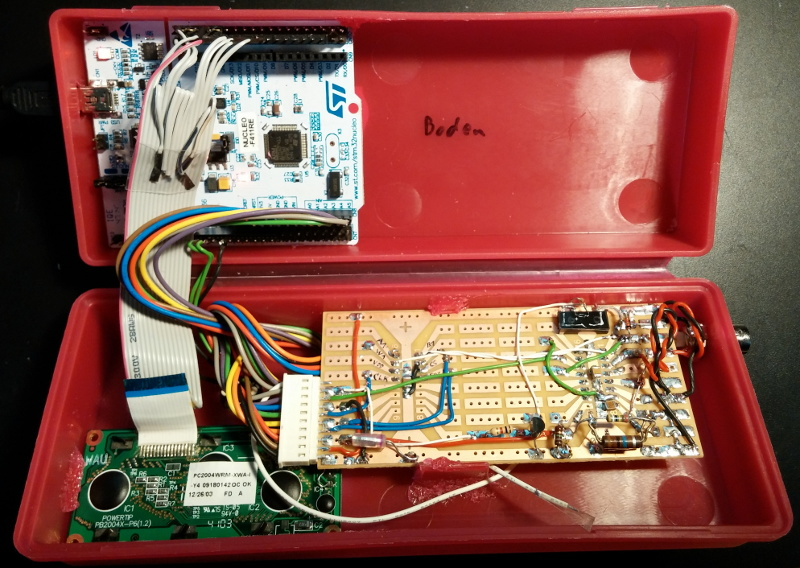
There is one exotic part: an ECL XOR gate. ECL is a logic family that uses transistors in their active region to achieve very fast switching rates. By using an RC low pass filter on one input of the XOR gate and driving it with a pulse, the device can generate a variety of fast pulse lengths.
[Krampmeier] submitted the design for a contest, but will provide more details after the contest is done (and there is more detail further down in the same discussion thread). In addition, others mentioned links to other resources, including a cheap TDR with a Microchip PIC (the [Krampmeier] project uses an ST ARM board) and the obligatory video from [w2aew].
We’ve talked TDRs before, of course. We’ve even looked at a tricky case where it didn’t really help much.


Oddly enough, this is quite simiar to CW radar:
https://en.wikipedia.org/wiki/Continuous-wave_radar
In CW radar, the CW stands for Continuous Wave, and is used to measure speed, not distance. However, with the right modification, can CW radar measure distance?
Yes. Basically, this can be done by using a linear ramp waveform to sweep the VCO, causing the return signal to be at a different frequency to the transmitted signal, because it has been delayed. The frequency difference, taken from a mixer, is related to the distance.
It gets even better!!!!
Mix the return with original, take an FFT and…. you get the electrical density plot of the cable. You should be able to see the “there is a kink at 1.3m, another one at 3.6 and a break at 6.7m.”
The idea of a variable pulse length is very clever.
TL;DR
TDWR (Terminal Doppler Weather Radar)
When I built a similar device for my master thesis (a LIDAR using time of flight) I used one of the coolest circuits I’ve ever used: The TDC-GP21 from Acam. It measures time down to 45ps and costs about 10€. What you need more than this is some very nice amplifier (something I never managed to build). But I did measure the distance between two pin header pins using oversampling and the increased time the signal took. That was a really cool feeling.
Wow.
I’ve been fooling around with DWM1000 modules. It is a weird feeling writing code comments like “// Timer tick frequency 64GHz” :)
I’m working on something similar as part of my PhD, would you be able to provide a link to your Thesis?
Thanks!
It’s published at Chalmers university of technology, so you should be able to search for it in some database (a long time since I did this). I think the name of the paper was Development of a low-cost laser rangefinder (LIDAR) or something similar.
Microchip has a peripheral called the CTMU that in single shot measurements can measure down to 50pS. In averaging it can obtain 5pS. It avoids the need for a 1GHz clock and can be calibrated using software to ~1%. Cost depending on MICRO can be less than ~ $2.00
The CTMU is very cool but I’ve not bee able to figure out how to set it up to measure time. Do you have any references?
We did look at the CTMU as a possible soultion for our project. Really neat thing with lots of applications, like solving world hunger.
@akismetuser212339447
I’ve been trying something similar but I have trouble setting up the thing (GP21), Do you have any code showing what you did? Much appreciated.
Looks interesting. He should change his user name though, at first I read Krapmeister :)
Speed of light is great and all, but you actually need to care about the speed of propagation. This depends on the cable, but typically is around 65% (for C5E cables).
Velocity factors of common coax (it’s the dielectric that determines it): http://www.repeater-builder.com/antenna/wa2ise-coaxial-cable.html
Speed of light in a medium is the speed of light in a vacuum, divided by the refractive index of the medium.
Give this man a cookie.
I know measuring cat5/6 cables, you can end up with different propagation rates from manufacturer to manufacturer, even for the same cable spec! (it only ends up resulting in an error of a few feet or so but that can make a difference when trying to find a break inside of a ceiling.)
There is another, simpler and cheaper method. The CTMU on available on some PICs can be used as a very fast switching current source.
It works by sending out a pulse, which triggers the current source to start charging a cap. You then have a comparator that looks for the reflection and triggers the current source to stop. Lastly, you measure the capacitor’s charge with an ADC to get your time measurement. My Dad and I were able to get resolutions of about a mm with this method.
We were originally targeting automotive, but I think there’s a few coffee makers and washing machines that use this now.
http://www.edn.com/design/sensors/4433411/Use-Time-Domain-Reflectometry–TDR–for-low-cost-liquid-level-measurement–Part-III
I haven’t been able to figure out how to measure time with the CTMU. Do you have any references?
“A time domain reflectometer, or TDR, is an essential piece of test gear when working on long cables.”
Also essential for high speed PCB design. I used to use a TDR all the time to do gigahertz backplane design. Helps determine if the PCB fabricator was able to keep your transmission line impedance accurate and whether the connector manufacturer was telling the truth about connector impedance.
If you’re not sure, just remove that piece of loose components and wiring and see if the phone still works.
Then the time difference between the reflection and the continuous run is measured. This helps in determining the distance to the anomaly.
Take a look: Reflectometry
Really amazing post..and nice information.Thanks for sharing.
Is the youtube video available elsewhere? It says “this video is unavailable”