The only useful data you’ll ever find is already digitized, but a surprising number of gauges and meters are still analog. The correct solution to digitizing various pressure gauges, electric meters, and any other analog gauge is obviously to replace the offending dial with a digital sensor and display. This isn’t always possible, so for [Egar] and [ivodopiviz]’s Hackaday Prize entry, they’re coming up with a way to convert these old analog gauges to digital using a Raspberry Pi and a bit of computer vision.
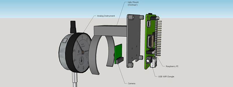
The idea behind this instrument digitizer isn’t to replace the mechanics and electronics, as we are so often wont to do. Instead, this team is using a 3D printed bracket that mounts a Raspberry Pi and camera directly in front of an analog gauge. Combine this contraption with OpenCV, and you have a device that’s just smart enough to look at a needle on a dial, convert that to a number, and save it to a file or send it out over WiFi.
It’s an extremely simple device for what [Egar] and [ivodopiviz] admit is a relatively niche application. However, if you only need digital measurements of an analog meter for a month or so, or you don’t want to mess up your steampunk decor, it’s an ingenious build.


Great Idea. A recommendation: The front ring of the dial can be turned to adjust the scale so better clamp it on the main housing. The offset is no longer required because it can now be done in software. And please don’t 3d-print the parts, make them the proper way :)
Its a splendid idea, but i think it is a bit much to put multicore linux computer for such an easy task. I see the point of the method as it is very lazy on engineer and easily customizable, but there is no point using anything more than esp wifi chip with optional cheap embedded arm. But using such approach requires analysis of a problem and simplification of method, and not the lazy approach.
The main reason here is probably cost… a digital “dial indicator” costs several times more then its mechanical brother if it’s supposed to have the same accuracy. And it’s usually not possible to just hook it up to extract the data…
Nice project, but isn’t a raspberry pi a bit oversized?
Current consumption, price!, size?
There are pretty small controllers, with USB and enough power to solve this problem!
The open cv solution is a good example of using open source technology, but I think in a second iteration there are many possible alternatives!
Keep on the good work!
“The only useful data you’ll ever find is already digitized”
I thought this was sarcasm but from the rest of the article it seems sincere
who comes up with this tripe
I have to agree…have you ever read a book…? Apparently you never saw paper or analog computers or a multitude of tons of thing that isn’t digital…please pull head from rectum when writing professional articles.
But how acurate is reading if dial is moving rapidly?
Good point, but in the case of the dial indicator, the plunger is typically lowered onto the object set in place to make the measurement so the needle settles in a fixed position. If there were very rapid movement, it could be possible that the plunger loses contact with the surface rendering the measurement useless. In the case of rapid movement, other types of sensors would be better suited and many of those already produce an analog or digital signal that can be recorded directly by a microcontroller.
OpenCV does live video, so with an appropriately fast cpu/algorithm you could analyze all 30 (or whatever) frames of the guage and average the results. That’s got to be similar to some digital guages for accuracy.
I’d say it’s a rather “brain” overkill (a raspi for that??) but lacking eye (the camera …).
On the rather crude mockup :P i’m missing …
– Some form of lighting (some LED+difusers) to ensure readability independently of room conditions.
– Macro lense or or an adjustable addon for the camera to ensure non-blurry measurements.
– Some blunt calculations on weight and power consumption (! adding weight to a mesuring tool … careful!).
– Casing for the raspberry pi itself.
– Costs estimation (isn’t that the main objective of the project?)
– Computer power estimation (Computer Vision takes its heavy toll… seriously).
But still, quite impressed with this project. They’ll face some difficult hurdles along the way, there’s a reason native-digital dials cost a bit bit more than their analog ancestors. They’ll learn a lot.
Nice
As a pragmatic engineer, this is how I would do it. Processing overkill is a nonissue when the hardware is so cheap and you can easily leverage proven libraries. This saves a lot of money in development time.
or, You could try using linear CCD to look at movement of the shaft and count pixels, couldn’t You?
Could this read my wristwatch for me?
I get the application for home automation fans and others who can’t modify the equipment(ie power meters) in question, but for the vast majority of everyone else there’s surely a sufficiently accurate digital version?
The whole computer vision aspect is imo worth the effort regardless.
Where is the lighting? It needs it’s own illumination and it has to be done right or you get a reflection of the dial face.
analog water meters have integrated magnet and ‘impulses’ can be read inductively
other analog meters often have silver cestion of a spinning disk designed to bounce led light, again no need for camera
I think you may reach same goal for lesser price and much lesser energy using an ArduCam and ESP8266 and some RTC module to schedule power on/off and send the picture somewhere else to a more “powerfull” server that will compute the analog-to-digital convertion using OpenCV that should also work for analog rolling digits counters.
http://www.arducam.com/arducam-supports-esp8266-arduino-board-wifi-websocket-camera-demo/
25 something for a camera with fpga and some controller, seems more powerfull than a EPS8266. cant you make it with wifi included? I dont get these more expensive external kits that get operated by a arduino only because the arduino should be the brains. A raspberry might be overkill but select the right mcu that can talk to a cmos camera and do some wifi and your done. Dont hold on to your “school” hardware because your love for it, look further. (especialy the fpga’s on the back look overkill to me, if the price was below 15, then maybe)
I am not an ESP8266 lover but I like this small and cheap chipset that inlude 80Mhz CPU+4MB Flash Storage+WiFi for $3 that make it more powerfull solution than Arduino (depending your needs) and many time ESP is only used as a simple serial-to-wifi gateway.
But all this could also be replaced by a very cheap and basic IPCam that will only be used to get time-to- time picture and manage it server side.
And this is the point, I don’t think the processing/analysis power should be located on camera’s side.
Small stepper / servo (or simple DC motor with a sync point) with an arm that walks a Hall sensor around the edge of the dial, picking up the needle (usually metallic, in my experience) and any 8-bit MCU to drive it all. Done!
Can the pi have a lo res display attached to allow for manual reading of the valve in real time?
I have this water meter, that i would like to “digitize”. It’s in such a bad location, that i need a pocket camera/cell phone to read it.
I was thinking of using mouse sensors, which i have 2 boxes of, and i can get lenses from mouses in which the chips don’t have a datasheet to know how to read the image of.
The big but is still the lenses. the meter has 4 digits (or 5, i forgot, probabably 4). But the sensors are wider, so i would need to overlap them, which would mean i probably need other kind of lenses for half of them.
I was thinking of using ESP8226, since it’s pretty fast + wifi + very small. Reading would either occur only when requested or not very often anyway. Would be nice to have OCR to be able to log stuff, but i guess just being able to read the image of a ESP webpage would be enough for now.
Instead of the mouse chips, i could use a camera, but ESP does not have USB interface. Maybe connecting the USB through serial, but then i would have to write a complete driver for the webcam, or port VUSB and still probably have to write a driver. Besides, the webcam would have to be really close to the gauge, since there is not much room, so maybe again i would have a lens issue.
I just looked and found some cheap GC0309 vga camera modules, but yeah, as i was afraid of, 30cm minimum focusing distance. I probably have 10cm, if i’m lucky. But atleast it has a i2C or something like that. I need to look into it more, when i have time.
Check the lens module of the camera, you may be able to change the focus depth if you can screw/unscrew the optic and looking at some picture of the GC0309 I see 3 spikes that may be used to screw/unscrew.
ESP8266 have no USB interface but you can connect SPI camera modules (like the link in one of my previous comments).
Another reason i was looking at ESP8266 was because it should have enough processing power to OCR the couple numbers, but i tried to search for a OCR software for microcontroller, but couldn’t find any. I don’t have anything more powerful running at my home 24/7 that i could offload the OCR to, so at this point i guess i have to forget it.
You are correct, given the dial’s limited number of states you should be able to train a neural network to recognise all of them very efficiently and compactly. But you will need to retrain it for each type of dial. Furthermore as I pointed out earlier controlling the lighting conditions when the frame is grabbed is very important.
ok everyone here has wayy more knowlage on this stuff than i do but im going to throw a cupl of ideas out there since i myself am going to attempt a simular build where the application will be measuring pressure < 600psi … im going to start with a transducer attatched via usb then have it transmit wirelessly the milliamp measurement which is convertible to PSI … i dont know how to code, i am familliar with different OS's and the install of most nessc components etc as am i an HVAC tech.. any ideas ? if software had to be made i could see the camera over analog guage as a dev tool for sure… all the "smart " tech tools for an hvac tech are xpensive as hell and shortcoming in my opinion.. 2 transducers = 60.00 a rasp pi maybe 60.00 and assured to have way more capability than a 500.00 tool from a box co.
any ideas are welcome